CMPUT 229 - Computer Organization and Architecture I
Lab 4: Game of Life Bytes
Creator: Nathan Ulmer
Introduction
In this lab you will create an interactive simulation of Conway's Game of Life. This simulation will require the use of RISC-V's interrupt handling facilities, as well as interfacing with external input and output devices.
Conway's Game of Life
John Conway invented the Game of Life in 1970 while attempting to simplify an earlier proposal by John von Nuemann about self replicating machines. Conway invented a simulation that follows the evolution of a square grid of cells. Each cell can be either living or dead. Conway devised a simple set of rules that would allow for patterns of these cells to become self replicating. These rules were based on a cell's state, and the number of living neighbours (any of the 8 cells surrounding it) that the cell has. The rules are:
- A living cell that has strictly less than two living neighbours dies.
- A living cell that has strictly more than three living neighbours dies.
- A dead cell that has exactly three living neighbours becomes alive.
- Otherwise, the cell's state doesn't change.
These simple rules lead to chaotic and emergent patterns of behaviour. The following animation shows a "glider gun"; a structure that produces an infinite number of moving groups of cells:
More complicated structures are possible, including a Turing Machine, and the Game of Life implemented in the Game of Life.
Example Execution
The simulator maintains a grid of cells, each of which is living or dead. A single iteration of the simulation causes each cell to be updated according to the rules of the Game of Life. The edges of the simulation grid "wrap around". For example, if you consider the cell in the top right corner, and move one cell to the right, you will end up at the top left corner. A more formal description can be found in the Game of Life Simulator section.
When running your simulator, provide the path to the input text file using the program arguments in the RARS simulator. The simulator starts in a paused state, displaying the contents of the input file.
Each cell in the terminal represents a single cell in the Game of Life
simulation.
Cells printed using the ' ' character represent cells that are
dead, while cells printed with the '#' character are alive.
The '|' character shows the cursor which is used to interact with
the simulator.
The cursor is displayed on top of all other cells.
The cursor can be moved up, down, left, and right using
the w, s, a, and d
keys respectively.
The cell that the cursor is on can be made living using the j
key, and dead using the k key.
Pressing the space key performs a single iteration of the simulation.
The simulation can be toggled from the "paused" state to the "running" by
pressing the t key.
While the simulation is in the "running" state, an iteration of the simulation
is performed once every second.
Finally, pressing the q key exists the simulation.
Interrupts
Control and Status Registers
This lab uses interrupts to help interface with the hardware. The following CSRs (Control and Status Registers) are important for the use of interrupts.
-
ustatus(User Status Register,CSR #0) is a 32-bit register that controls and manages user-level interrupts. To enable user-level interrupts set the 0th bit of this register to 1. -
uie(User-Interrupt Enable Register,CSR #4) is a 32-bit register that controls the types of interrupts that are enabled using a bitmask. Bits 4 and 8 are relevant for this lab. The 4th bit enables user-level timer interrupts. The 8th bit enables user-level external interrupts. These bits must be set to 1 to enable interrupts from the timer and the keyboard. -
utvec(User Trap-Vector Base-Address Register,CSR #5) is a 32-bit register that controls where interrupts are handled. This register holds the address of the interrupt handler that should be called when an interrupt or exception occurs. -
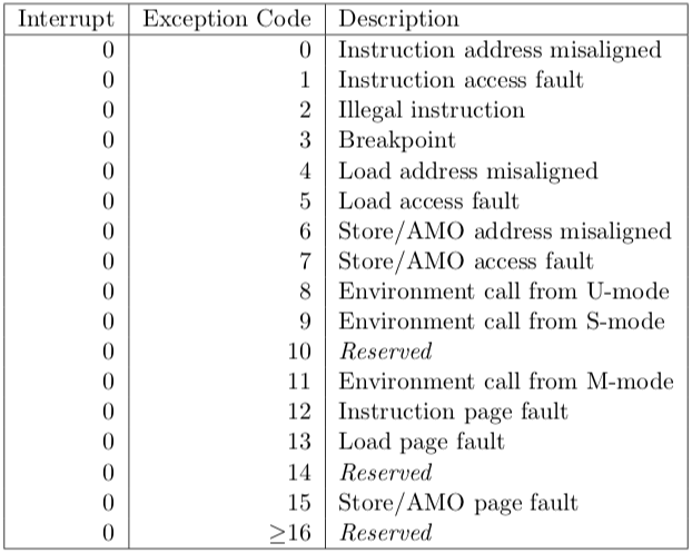
ucause(User Trap Cause Register,CSR #66) is a 32-bit register that identifies which type of interrupt is being handled. After an exception or an interrupt, this register holds the interrupt/exception code. This is useful for identifying the type of the interrupt/exception. The code is stored in the first 31 bits ofucauseand the highest bit indicates whether it was an interrupt or an exception. To check what type of interrupt/exception occurred, refer to the following table. -
uscratch(User Scratch Register,CSR #64) is 32-bit register that holds a value for use by the interrupt handler. The usage of this register is described in detail in this section.
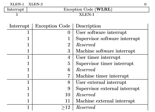
The exception codes for the "User timer interrupt" and "User external interrupt" are relevant for this lab.
These CSRs can be set using the CSR instructions.
For example, to enable user-level interrupts in ustatus use the
"CSR Read/Write Immediate" instruction: csrrwi zero, 0, 1.
Or use pseudo-instructions to read and write to the CSR registers.
For example:
  csrr  t0, 4       # Read from CSR #4 to t0
  csrw  t0, 6       # Write t0 into CSR #6
  csrwi 0, 0x4      # Write 0x4 into CSR #0
Once an interrupt is raised it must be handled in the interrupt handler
created in this assignment.
An interrupt handler is analogous to a normal function but there are some key
differences.
An interrupt can occur at any time, thus the handler must guarantee that all
registers are restored to their original values after the handler finishes.
Therefore, the handler must save any register that it uses (not just
the s registers) and the handler must restore the original values
to these registers before returning.
The instruction uret must be used to leave the interrupt handler
instead of the jr ra or ret instructions that are
used to return from a normal function.
Furthermore, you should not call functions exterior to the
handler if they use the user stack pointer.
Refer to the Writing an Interrupt Handler section
for more information.
Keyboard & Display
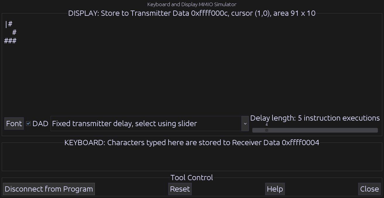
Use the Keyboard and Display MMIO Simulator, available under the
"Tools" menu in RARS, to interact with the simulator.
The contents of the terminal are shown in the display section, and keys are
typed in the keyboard section.
Be sure to click "Connect To Program" after assembling the program and before
running it.
If you resize the window, click the "Reset" button to propagate the size
change.
Generally, devices have two registers associated with them, a control, and a data register. The control register relays information about the device's state, and the data register relays data to or from a device. A description of the control and data registers for the keyboard and display can be found in the Memory-Mapped IO section.
A separate keyboard interrupt occurs for every key pressed when keyboard interrupts are enabled. Therefore, the user program receives input one character at a time.
Timer
In RISC-V, timing functionality is managed by the timing hardware thread.
The timing hardware thread maintains the time asynchronously, and allows the
program to raise an interrupt at a specific time.
To do this the core keeps track of the time in the 64-bit
register time which holds the current time (in milliseconds)
since the program started.
To generate a timer interrupt at a specific time, the value in the
register timecmp must be set.
Each time a timer interrupt occurs, you must set the timecmp
register with a new time to generate a subsequent timer interrupt.
A description of the registers can be found in
the Memory-Mapped IO section.
To simulate RISC-V timing functionality use the Timer Tool under
the "Tools" menu in RARS.
Be sure to click "Connect To Program" and "Play" after assembling the program
and before running it.
Memory-Mapped IO
Memory-mapped IO allows the interaction with external devices through an interface pretending to be system memory. This mapping allows the processor to communicate with these devices using the load-word and store-word instructions. Here are the memory mappings and descriptions of important IO registers for this lab:
| Register | Memory Address | Description |
|---|---|---|
| Keyboard Control | 0xffff0000 |
For keyboard interrupts to be enabled, bit 1 of this register must be set to 1; after the keyboard interrupt occurs, this bit is automatically reset to 0. |
| Keyboard Data | 0xffff0004 |
The ASCII value of the last key pressed is stored here. |
| Display Control | 0xffff0008 |
Bit 0 of this register indicates whether the processor can write to the display. While this bit is 0 the processor cannot write to the display. Thus, the program must wait until this bit is 1. |
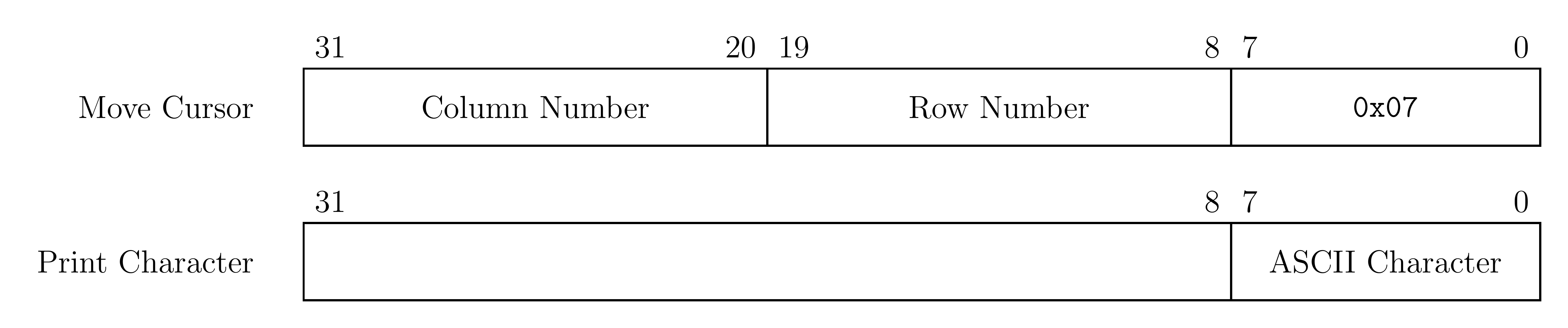
| Display Data | 0xffff000C |
When a character is placed into this register, given that the display
control ready bit (bit 0) is 1, that character is drawn onto the
display.
If the character is the bell character (ASCII code 0x07)
the display will move the cursor and the bits 8-19 and 20-31
correspond to the row and column respectively.
|
| Time | 0xffff0018 |
This is a read-only register that holds the time since the program has started in milliseconds. |
| Timecmp | 0xffff0020 |
When the value in this register is less than or equal to the value
in time a timer interrupt occurs.
Writing to this register is required to set up a timer interrupt.
|
The layout of the display data register is shown in the following graphic:
For your convenience, the addresses of each IO register are given in the
following variables in the common.s:
| Register | Global Variable |
|---|---|
| Keyboard Control | KEY_CONTROL
|
| Keyboard Data | KEY_DATA
|
| Display Control | DISPLAY_CONTROL
|
| Display Data | DISPLAY_DATA
|
| Time | TIME
|
| Timecmp | TIME_CMP
|
Writing an Interrupt Handler
When an interrupt is raised, the program is paused and execution is
transferred to the interrupt handler.
The utvec register holds the address of the interrupt handler
that should be called when an interrupt or exception occurs.
To ensure that the program can safely resume execution after returning from
the handler, the registers used by the handler must be saved upon entering the
interrupt handler and restored before returning.
The registers cannot be saved using the stack pointer because the stack
pointer may be corrupted.
Therefore, in common.s we have allocated memory
labeled trap_data where your handler may save registers.
In common.s we have also placed the address
of trap_data into the uscratch register.
You can use the uscratch register and the csrrw
instruction to save and restore all the values of the registers used in the
handler.
The first and last instructions executed in the handler should
be csrrw a0, 64, a0, where a0 is chosen by
convention.
The following is some sample code that saves two registers for use in the
interrupt handler.
csrrw   a0, 64, a0      # Swap a0 with uscratch
sw      t0, 0(a0)       # trap_data[0] <- t0
sw      t1, 4(a0)       # trap_data[1] <- t1
...
Non-re-entrant handler: In such a handler interrupts are not
enabled during the execution of the handler.
Since only one interrupt will be processed at any given time, the memory
in trap_data can be used freely.
This type of handler is simpler to implement than a re-entrant handler.
Re-entrant handler: A re-entrant handler enables interrupts
during the execution of the interrupt handler.
The interrupt handler must use the memory in trap_data such that
an interrupt can occur during the execution of an interrupt handler.
This can be accomplished using an interrupt stack pointer.
At the start of the handler, space for registers are reserved on the
interrupt stack, and the interrupt stack pointer is updated.
Interrupts can then be safely enabled.
In this lab you are not required to implement a re-entrant interrupt handler.
It is not recommended for your handler to perform any simulation logic. Rather, your handler should notify the rest of your solution that an interrupt occurred, and provide any needed data.
Handling Additional Interrupts / Exceptions
When executing RARS with your own interrupt handler, runtime errors won't be
shown in RARS as usual.
Thus, a function that prints the line where an error occurred and the error
code is included.
This functionality is provided by the handlerTerminate function
in the common.s.
In your interrupt handler, call handlerTerminate if a
non-keyboard and non-timer interrupt occurs.
You can use the following table to identify the error:
Game of Life Simulator
This section describes the technical details of the simulator.
Simulating the Game of Life
On each iteration of the simulation, we apply a set of rules on each cell in the grid to compute the new state of the cell. The neighbours of a cell are the 8 cells that are directly adjacent or diagonal to a given cell. The rules are as follows:
- A living cell that has strictly less than two living neighbours dies.
- A living cell that has strictly more than three living neighbours dies.
- A dead cell that has exactly three living neighbours becomes alive.
- Otherwise, the cell's state doesn't change.
The initial state of the simulator is specified by the input file.
The input file is parsed, and the result is given to your solution in an
appropriately sized buffer by the code in common.s.
The code in the common.s also initializes a second buffer of
the same size.
These two buffers must be used to update the simulation.
If only one buffer is used, the partial update of that buffer could change the
neighbour counts of other cells, thus changing the results of the simulation.
To prevent this from occurring, for each simulation step, cells are read from
the current buffer and the computed result is written to the other buffer.
In the next step of the simulation, the roles of the two buffers are swapped.
The dimensions of the grid in this simulator are bounded. As such, it is ambiguous what the neighbour counts of cells on the edges of the grid should be. One possible solution is to have all cells outside of the grid register as always dead. However, in this simulator we will wrap the edges of the grid to their respective opposite edges.
The Cursor
The cursor is used to set cells as alive or dead while the simulation is
running.
The row position of the cursor is given in cursor_row variable,
and the column position is given in the cursor_col variable.
As you move the cursor, you must update the values in these
variables.
Cell Grids
The state of cells in the simulation are stored in a byte array, referred to
as a "grid".
Each cell in the grid has a coordinate of the form \((x, y)\), and the
top-left corner of the grid has coordinate \((0, 0)\).
The \(x\)-coordinate of a point increases as you move to the right and the
\(y\)-coordinate increases as you move down.
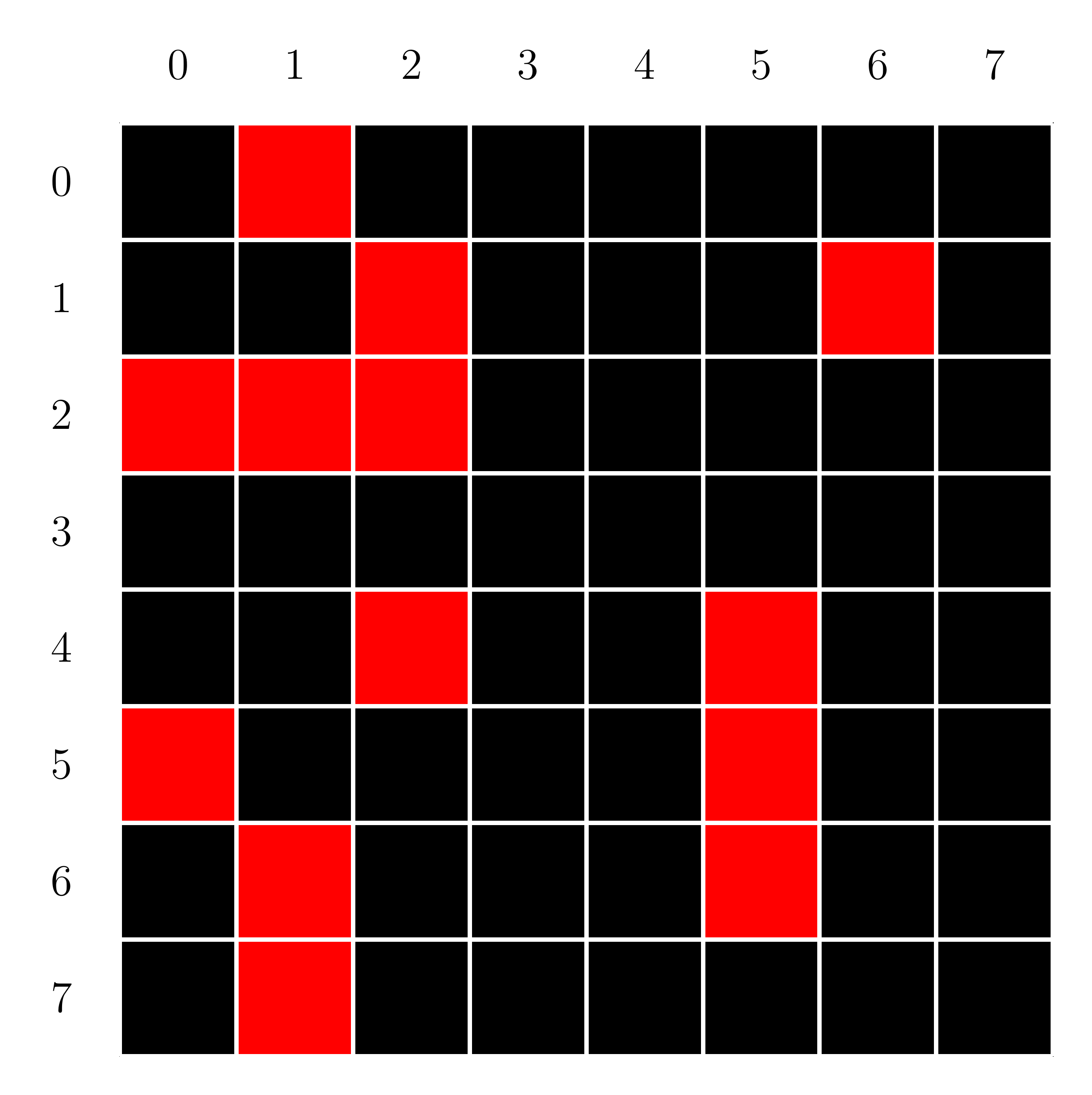
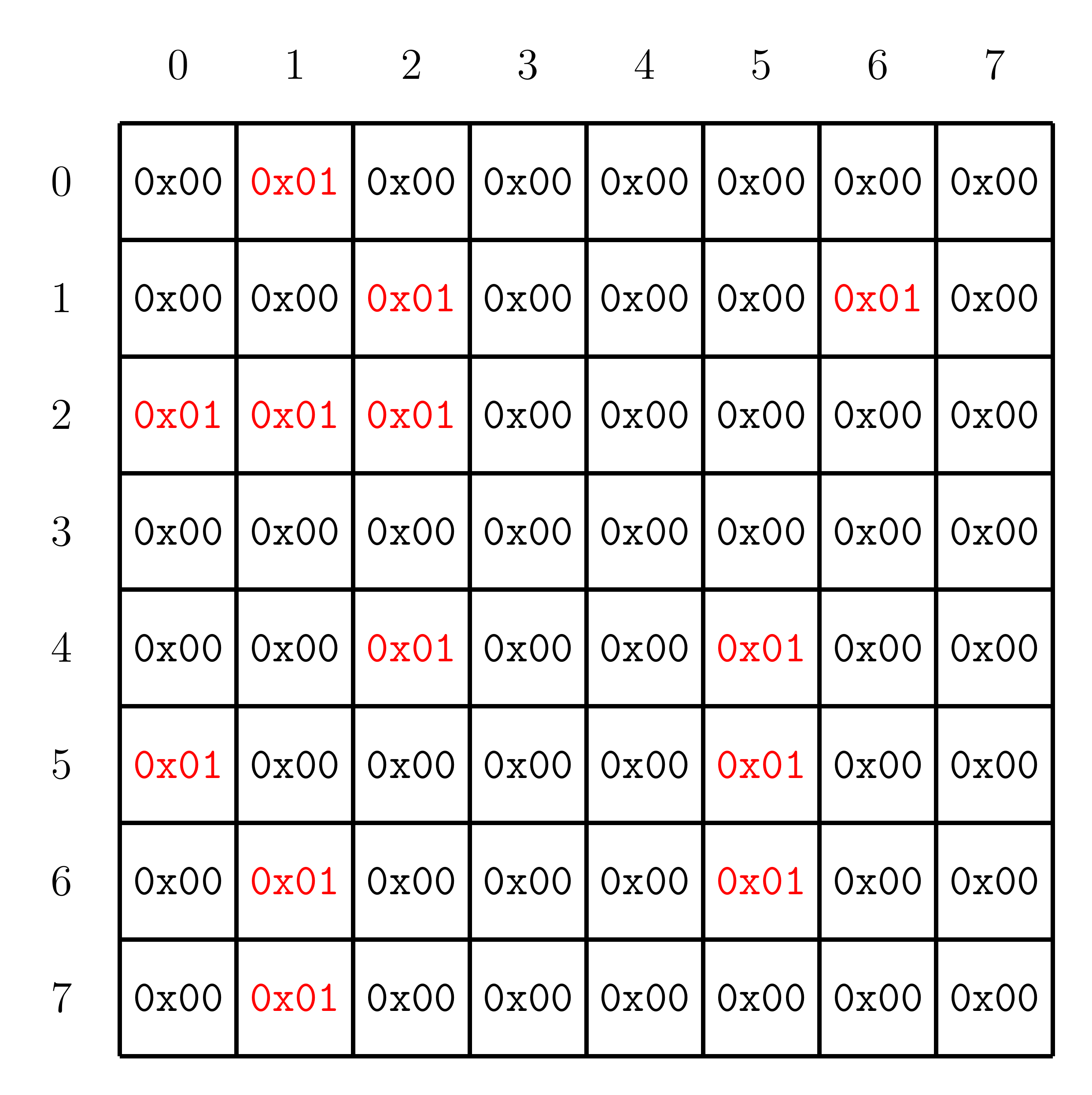
The byte 0x00 represents a dead cell, while the
byte 0x01 represents a living cell.
For example, consider the following left grid, where black cells are dead and
red cells are living.
The cell at \((0, 0)\) is dead, and the cell at \((1, 0)\) is living.
If we convert each cell to its corresponding byte, we obtain the right grid.
To store the grid into memory, we cut the grid up into rows and store the grid
using row major order into a continuous memory space.
Starting at address 0x10001000, the example grid will have the
following layout in memory:
| Address | Value |
|---|---|
0x10001000 | 0x00000100 |
0x10001004 | 0x00000000 |
0x10001008 | 0x00010000 |
0x1000100c | 0x00010000 |
0x10001010 | 0x00010101 |
0x10001014 | 0x00000000 |
0x10001018 | 0x00000000 |
0x1000101c | 0x00000000 |
0x10001020 | 0x00010000 |
0x10001024 | 0x00000100 |
0x10001028 | 0x00000001 |
0x1000102c | 0x00000100 |
0x10001030 | 0x00000100 |
0x10001034 | 0x00000100 |
0x10001038 | 0x00000100 |
0x1000103c | 0x00000000 |
Since each cell can only be either of two states, only a single bit is truly
needed for each cell.
Thus the above format is highly inefficient.
However, the inefficiency is offset by the ease of accessing the cells using
RISC-V's lb and sb instructions.
Wrapping the Grid
When traveling off the edge of the simulation grid, the simulation wraps
around to the opposite edge.
This must be considered when moving the cursor across the edge of the grid and
when computing the neighbour count of a cell.
In general, any point \((x, y)\) can be mapped onto the grid using the
following formula:
\[
(x \bmod c, y \bmod r)
\]
where \(c\) is the number of columns, and \(r\) is the number of rows.
For example, consider the following mappings for a \(4 \times 4\) grid:
\[
\begin{align*}
(3, 1) &\quad\rightarrow& (3 \bmod 4, 1 \bmod 4) &= (3, 1) \\
(5, 4) &\quad\rightarrow& (5 \bmod 4, 4 \bmod 4) &= (1, 0) \\
(-1, 2) &\quad\rightarrow& (-1 \bmod 4, 2 \bmod 4) &= (3, 2)
\end{align*}
\]
However, in the context of this simulator, we are only concerned with points
that are in the grid, or outside of it by one tile (including the corners).
Thus your solution need only handle these cases and not the more general
wrapping.
Note that the RISC-V rem instruction is not
equivalent to the modulus operation.
Display
At the start of the simulation, and after each update, the grid of cells must
be printed to the MMIO display.
For your convenience, we provide the following function in
the common.s to print a single character to a given location on
the display.
printCell
  Print a character to the MMIO text terminal at (row, col)

  Arguments:
    a0: Character to print as an ASCII byte
    a1: Row to print the character at
    a2: Column to print the character at

  Returns:
    N/A
The cursor should be printed over top of all other characters.
The characters for living cells, dead cells, and the cursor are stored as
single bytes at the ALIVE_CHAR, DEAD_CHAR,
and CURSOR_CHAR variables in the common.s.
Timing
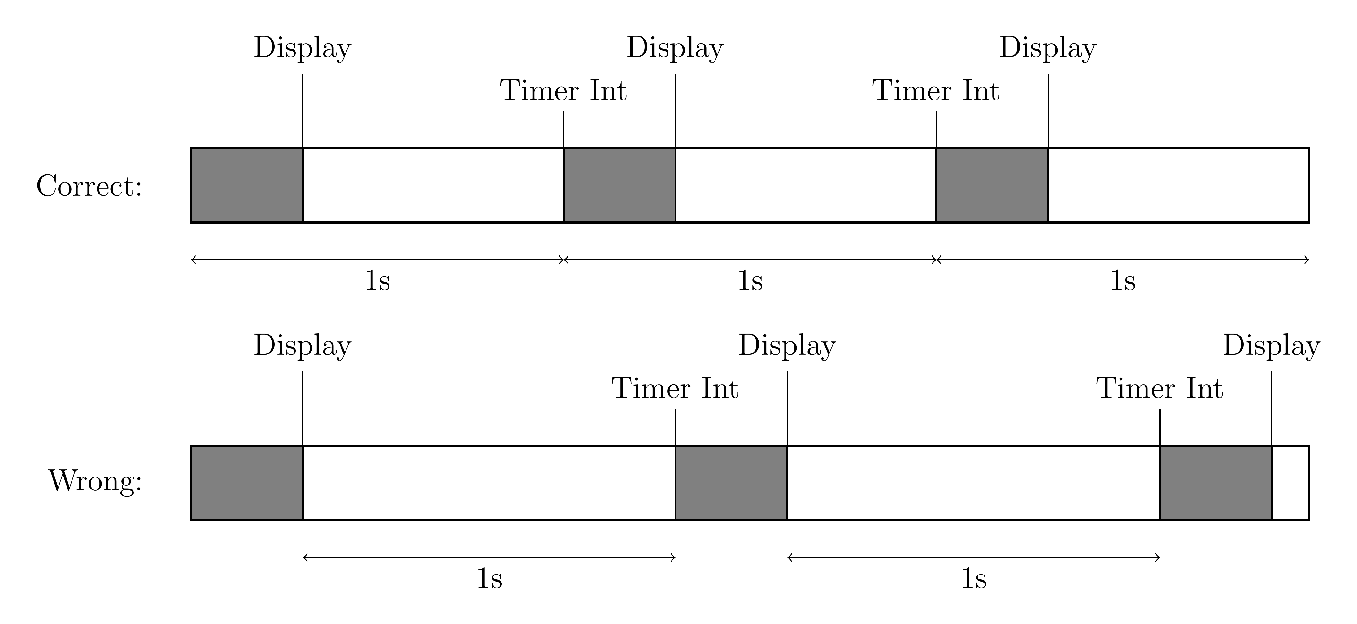
When the simulator is in the "running" state, an iteration of the Game of Life rules is performed once per second. The timer should be reset before beginning to update the simulation. Otherwise, the time between updates will include the time taken for your solution to update the simulation. This can noticeably increase the time between updates.
This problem is illustrated in the following figure. The shaded gray boxes represent the time taken by the simulator to step the simulation and display the results. The "Timer" label shows when a timer interrupt occurs. In the "Correct" scheme, when a timer interrupt occurs, the simulator resets the timer directly. Thus the one second delay includes the time taken for the simulator to run. However, in the "Wrong" scheme, the timer is set after the simulator has updated. Thus the total time between display updates is longer than one second.
Controlling the Simulator
The simulation is interacted with using keyboard controls. The controls for the simulation are as follows:
-
w: Move the cursor up one character, wrapping if needed, and update the display. -
s: Move the cursor down one character, wrapping if needed, and update the display. -
a: Move the cursor left one character, wrapping if needed, and update the display. -
d: Move the cursor right one character, wrapping if needed, and update the display. -
j: Set the cell at the current cursor position to be living. -
k: Set the cell at the current cursor position to be dead. -
t: Switch the state of the simulation between "paused" and "running". If the simulator is switched to the "running" state, the next update should happen in one second. -
space: If the simulation is in the paused state, perfom a single step and update the display. Does nothing if the simulator is in the "running" state. -
q: Exit the simulation and return control to the code incommon.s.
All other keyboard input should be ignored.
For your convenience, the following variables in
the common.scontain the ASCII character for a given control:
| Control | Global Variable | ASCII Value |
|---|---|---|
w
| UP
| 0x77
|
s
| DOWN
| 0x73
|
a
| LEFT
| 0x61
|
d
| RIGHT
| 0x64
|
j
| ALIVE
| 0x6a
|
k
| DEAD
| 0x6b
|
t
| TOGGLE
| 0x74
|
space
| STEP
| 0x20
|
q
| EXIT
| 0x71
|
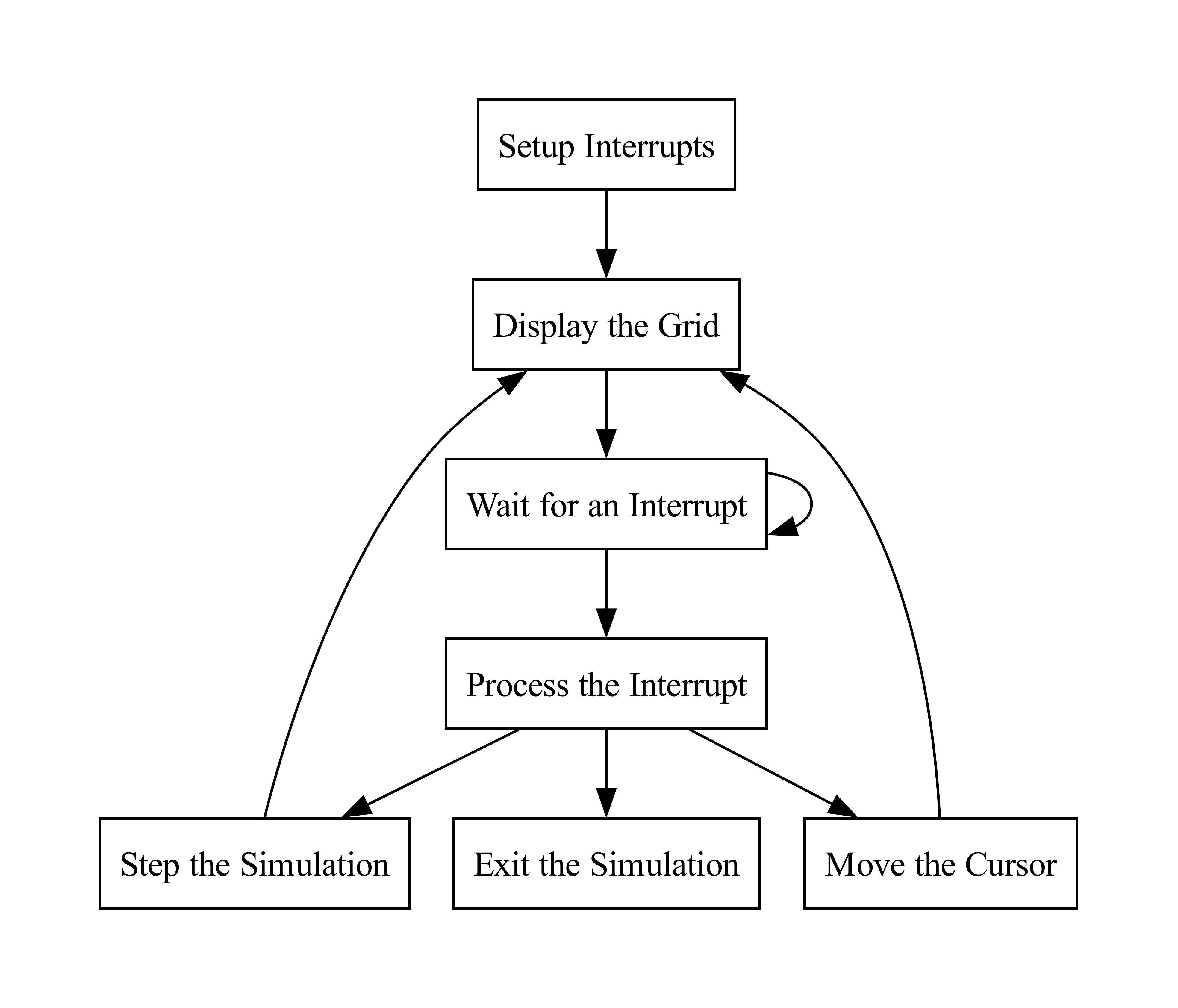
Flow of the Simulator
The flow of the non-interrupt handler portion of the simulator is given in the following diagram:
Assignment
This lab implements a series of functions to create a simulator for the game of life. You are required to implement all of the following functions:
gameOfLife
  This function serves as the entry point for the Game of Life simulator.

  Arguments:
    a0: Number of rows in the grid
    a1: Number of columns in the grid
    a2: Pointer to grid buffer A (Initialized with input state)
    a3: Pointer to grid buffer B

  Returns:
    N/A
displayGrid
  Display the input grid to the MMIO terminal.

  Arguments:
    a0: Number of rows in the grid
    a1: Number of columns in the grid
    a2: Pointer to grid buffer to display

  Returns:
    N/A
updateGrid
  Perform a single Game of Life simulation step. This function reads from one
  grid buffer and writes the result to another.

  Arguments:
    a0: Number of rows in the grid
    a1: Number of columns in the grid
    a2: Pointer to the input grid buffer
    a3: Pointer to the output grid buffer

  Returns:
    N/A
getCell
  Get the value of a given cell. If the location is out of bounds, wrap around.

  Arguments:
    a0: Number of rows in the grid
    a1: Number of columns in the grid
    a2: Row of the cell
    a3: Column of the cell
    a4: Pointer to the grid buffer

  Returns:
    a0: Value of the cell
setCell
  Set the value of a given cell. If the location is out of bounds, wrap around.

  Arguments:
    a0: Number of rows in the grid
    a1: Number of columns in the grid
    a2: Row of the cell
    a3: Column of the cell
    a4: Pointer to the grid buffer
    a5: Value to set the cell to

  Returns:
    N/A
handler
  Interrupt handler.

  Arguments:
    N/A

  Returns:
    N/A
Writing a Solution
The directive .include "common.s" at the start of the solution
file causes the assembler to insert the code present in
the common.s file at the start of the solution.
The code in the common.s file reads the program arguments and
loads the corresponding file.
The file is then parsed and given to gameOfLife as input.
The code in common.s serves as the entry point, and takes care of
calling gameOfLife with the correct augments.
The code in common.s also handles the parsing of the input file,
and initializes uscratch.
Be sure to follow the RISC-V register calling conventions for all functions in
your solution.
Arguments to functions and return values should be passed in
the a0-a7 registers.
Testing your Lab
We have provided a small number of sample inputs to you, located in
the Tests/ directory of your repository.
The sample inputs provided are not extensive.
Be sure to create your own inputs to ensure that your solution is correct.
Input files are given as *.txt files, with the following format:
[# of rows]
[# of columns]
[First row of initial state]
...
[Last row of initial state]
Each row of the input state contains a '#' if that cell is
living, and a space otherwise.
If the length of a line is less than the number of columns, the missing cells
are assumed to be dead.
Similarly, if the number of lines is less than the number of rows, all missing
cells are dead.
The length of all lines describing the initial state should be less than or
equal to the number of columns in the grid.
For example, the following initializes a glider in the top left corner using a
5 by 10 grid.
5
10
 #
  #
###
Assumptions and Notes
- Both the number of rows and the number of columns will be positive integers strictly greater than zero and less than or equal to 50.
-
The
getCellandsetCellfunctions only need to handle wrapping of cells outside of the grid by a single tile, including the corners. - Your solution need not print cells in any particular order, so long as the output is visually correct.
- The simulator should start in the "paused" state and not the "running" state.
Resources
Marking Guide
Assignments too short to be adequately judged for code quality will be given a zero for that portion of the evaluation.
-
25% for non-visual functions:
- 15%
updateGridsteps the simulation correctly. - 5%
getCellworks correctly. - 5%
setCellworks correctly.
- 15%
-
55% for the interactive simulator:
-
20% for user interaction:
- 4% for correct cursor movement.
- 4% for correct cursor wrapping.
- 4% for setting cells as living or dead.
- 4% for toggling between simulation states.
- 4% for exiting the simulation.
-
35% for simulation and display:
- 5% for correct display of initial state.
- 10% for correct single stepping of the simulation.
- 20% for correct operation in the "running" state.
-
20% for user interaction:
- 20% for code cleanliness, readability, and comments.
Submission
There is a single file to be submitted for this lab.
gameOfLife.s should contain the code for you solution.
-
Do not add a
mainlabel to this file. -
Do not modify the line
.include "common.s". -
Keep the file
gameOfLife.sin theCodedirectory of your repository. - Push your repository to GitHub before the deadline. Just committing will not upload your code. Check online to ensure that you solution is submitted.