This lab introduces the ARM assembly language and asks you to write a program that translates a subset of RISC-V assembly into ARM assembly. This lab is the first of two ARM translation labs. This lab focuses on the translation of ALU instructions. The next lab, Lab ARM - Control, will translate control-flow instructions.
The ARM instruction set varies in quite a few ways from the RISC-V
instruction set. It aims to cause fewer control-flow changes and
pipeline flushes during the execution of the program. ARM has only 15
visible registers at any time, numbered R0 through
R14. Of these, R13 is the
Stack Pointer, equivalent to RISC-V's sp, and
R14 is the Link Register, equivalent to RISC-V's
return address (ra) register. ARM also operates with 4-byte
words.
The binary code for every ARM instruction begins with a 4-bit condition
code that determines whether or not that instruction should execute. The
binary format for a data processing instruction --- which supports
ADD, SUB, OR and other ALU
instructions with an immediate value --- is as shown below:

Conditions (bits 31-28) allow the instruction to
be executed conditionally. The purpose is to get rid of branching,
which can introduce delays when the outcome of the branch is predicted
incorrectly. This conditional execution of instructions is called
predicated execution because the condition can be seen as a
predicate that controls the execution of the instruction. For the
purposes of this lab, the conditions field for every instruction
should be 1110 which allows for every instruction to
always get executed. The next lab will elaborate on the conditions
field and the various related flags.
Bits 27-26 are 00 for all
data-processing instructions. Bits 27-25 are part of another opcode,
with 00x representing data-processing and miscellaneous
instructions, where x specifies how the operands are
supplied to the instruction.
Immediate (bit 25) specifies whether the operands
are two registers or a register and an immediate value. A 1 specifies
an immediate value, while a 0 specifies an additional register.
Opcode (bits 24-21) specifies the type of
operation to perform on the two operands. Relevant opcodes are
detailed later on.
Status (bit 20) determines whether the outcome of
this instruction alters the Status register, which is
used by control-flow instructions. Control-flow instructions will be
translated in the next lab. The Status bit should be 0
for all instructions in this lab.
Rn (bits 19-16) contains the first operand for the
ARM instruction.
Rd (bits 15-12) is the register that contains the
output of the instruction.
Rotate (bits 11-8) The instruction uses a 32-bit
immediate value, however only 8-bit immediate and 4-bit rotate fields
are specified. To obtain the immediate, the value in the 4-bit rotate
field is first shifted left a single bit and then that value is used
to shift the 8-bit immediate right, with wraparound. Though this means
that only some 32-bit immediates are possible, it allows for large
powers of 2 to be more easily represented. The following gif
illustrates the rotation.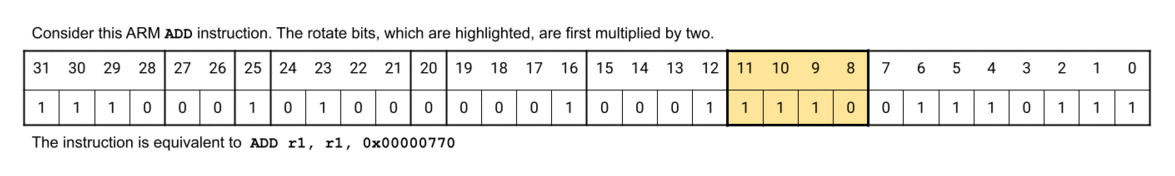 First, the value in the 4 rotate bits is multiplied by 2 (or,
equivalently, shifted left by a bit). Here, the value obtained after
this shift is 28. Thereafter, the value in the 8 immediate bits,
First, the value in the 4 rotate bits is multiplied by 2 (or,
equivalently, shifted left by a bit). Here, the value obtained after
this shift is 28. Thereafter, the value in the 8 immediate bits,
0x77, is shifted to the right with wraparound by the
value obtained from the previous calculation in bits. That is,
0x77 is shifted by 28 bits. The 32-bit value obtained
after this 4-bit shift with wraparound, 0x00000770, will
be used as the immediate in this instruction.
Immediate (bits 7-0) is an unsigned 8-bit value
that is rotated by the rotate field over 32 bits with wraparound, then
used as the 32-bit second operand in the operation specified by the
instruction.
The data-processing immediate format explained above is used by the ARM
instructions AND, OR, SUB and
ADD with a single register operand and an immediate value.
An addi instruction with a negative immediate must be
translated into the SUB instruction.
There may be multiple combinations of the ARM immediate + rotation field
values that will map to a RISCV immediate. In order to map RISCV
immediates correctly to their ARM encodings, be sure to follow this
rule:
You should follow the ARM convention such that if an immediate has
multiple possible encodings, the representation with the smallest
rotation value is correct.
For example: the correct immediate + rotation combination of input 0x800
will be:
immediate = 0000 0010
rotation = 1011
and the correct immediate + rotation combination of input 0xC will
be:
immediate = 0000 1100
rotation = 0000

This instruction format is for ARM data-processing instructions that use
two registers as operands. The immediate bit (bit 25) is set to
0, and bits 11-0 hold the register for the second operand
and a Shift field.
Bits 31-12 have the same fields as data-processing immediate instructions.
Rm (bits 3-0) is the second operand for the
instruction, after its content is shifted (see below).
Shift (bits 11-4)Rm prior
to the operation. When bit 4 is set to 0 the shift amount is in bits
11-7. When bit 4 is set to 1 the shift amount is in the lowest byte of
the content of Rs. Bits 6-5 specify the shift type as
shown in the Shift Types table above. Rotate right performs a
rightward shift in which bits that "fall off" the register are placed
entering the opposite side.
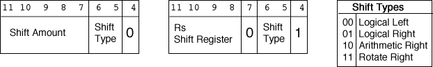
Specifying Rotate Right 0 in the shift field shifts
Rm rightwards 1, and places the Carry flag from the status
register into bit 31. Flags are explained in the Lab ARM Control.
The data-processing register format is used by ARM instructions
AND, OR, SUB and
ADD that use two register operands as well as for all
LSL, LSR and ASR instructions.
All (both I-type and R-type) RISC-V bit-shift operations should be
translated into data-processing register-format instructions. The
information in the Shift section describes how ARM
immediate-value and register-value shifts should be encoded.
Immediate shifts in the Shift field should not be encoded
with the function computeRotation specified below.
Immediate shifts should be written as is because both RISC-V and ARM
shift-immediate values are 5 bit fields treated as unsigned numbers.
For all bit-shift operations (i.e. LSL,
LSR and ASR instructions), bits 19 to 16 must
be 0 because RISC-V's R-type instructions do not have an immediate value
and therefore the shift field should be 0 for all
instructions that do not perform a shift. When necessary, the register
is specified in bits 11-8.
RISC-V instructions must be translated into the following ARM instructions in this lab:
| Instruction | Opcode | Description |
| AND | 0000 |
bitwise AND of two register values or of one register value and an immediate value |
| OR | 1100 |
bitwise OR of two register values or of one register value and an immediate value |
| ADD | 0100 |
addition of two register values or of one register value and immediate value |
| SUB | 0010 |
subtraction of one register value from another (specifically
Rn - Rm) or of an immediate from a register value.
|
| LSL | 1101 |
shifts register value in Rm left by specified number of
bits. has shift type 00
|
| LSR | 1101 |
shifts register value in Rm right by specified number
of bits without sign extension. has shift type 01
|
| ASR | 1101 |
shifts register value in Rm right by specified number
of bits with sign extension. has shift type 10
|
Your assignment is to implement a binary translator from RISC-V to ARM for a subset of RISC-V assembly instructions. The subset implemented in this lab is not Turing complete because it only consists of arithmetic and logic operators. Once you complete the next lab --- translating conditional operators --- then you will have a Turing-complete set of operators and could as such, theoretically, compute anything with that subset.
The following are all of the RISC-V instructions that you will need to
handle in your binary translator. Additional constraints are put on some
instructions to ensure simple translation to ARM instructions. In the
encoding, s specifies a source register, t a
target register, d a destination register and
i an immediate value.
| Instruction | Encoding | Type |
ANDI d, s, imm |
iiii iiii iiii ssss s111 dddd d001 0011 |
I |
AND d, s, t |
0000 000t tttt ssss s111 dddd d011 0011 |
R |
ORI d, s, imm |
iiii iiii iiii ssss s110 dddd d001 0011 |
I |
OR d, s, t |
0000 000t tttt ssss s110 dddd d011 0011 |
R |
ADDI d, s, imm |
iiii iiii iiii ssss s000 dddd d001 0011 |
I |
ADD d, s, t |
0000 000t tttt ssss s000 dddd d011 0011 |
R |
SUB d, s, t |
0100 000t tttt ssss s000 dddd d011 0011 |
R |
SRAI d, s, imm |
0100 000i iiii ssss s101 dddd d001 0011 |
I |
SRLI d, s, imm |
0000 000i iiii ssss s101 dddd d001 0011 |
I |
SLLI d, s, imm |
0000 000i iiii ssss s001 dddd d001 0011 |
I |
SRA d, s, t |
0100 000t tttt ssss s101 dddd d011 0011 |
R |
SRL d, s, t |
0000 000t tttt ssss s101 dddd d011 0011 |
R |
SLL d, s, t |
0000 000t tttt ssss s001 dddd d011 0011 |
R |
RISC-V destination registers should be encoded as Rds in
ARM. For all instructions but shifts, translated source and target
registers should be encoded as Rn and
Rm respectively.
For shift instructions, the source register should be encoded as
Rm and the target register should be encoded within the
Shift field as described above.
ADDI instructions are an exception to the no
negative immediates guarantee, as they can be converted into ARM
SUB instructions.
computeRotation function have a valid ARM
translation and fit into the 12 immediate bits of RISC-V I-type
instructions.
ADDI instructions the immediate values may be
a negative value represented in 2's-complement n. If the immediate
value of a RISC-V ADDI instruction is negative, that
instruction translated to an ARM SUB instruction.
function7 (i.e.
bit 30 is 1) which needs to be accounted for when extracting the
immediate.
S after the instruction type (e.g.
ADD S R0, R1, R2). It also indicates when a non-shift
data-processing register instruction has a shift by appending
LL/LR/AR/RR
alongside the shift amount at the very end of the instruction.
common.s file.
ecalls to help debug, make sure to
remove them before submitting your solution because it may result in
lost marks.
The ARM architecture exposes only 16 registers at a time to its instructions. A fully featured binary translator would need to recompute register allocation, which is beyond the scope of this assignment. Therefore, the translator will assume that only the RISC-V registers below appear in a valid RISC-V program.
| RISC-V Register | ARM Register |
t0 (x5) |
R0 |
t1 (x6) |
R1 |
t2 (x7) |
R2 |
s0 (x8) |
R3 |
s1 (x9) |
R4 |
s2 (x18) |
R5 |
s3 (x19) |
R6 |
s4 (x20) |
R7 |
s5 (x21) |
R8 |
s6 (x22) |
R9 |
a0 (x10) |
R10 |
a1 (x11) |
R11 |
a2 (x12) |
R12 |
sp (x2) |
R13 |
ra (x1) |
R14 |
You are required to implement the following functions:
RISCVtoARM_ALUa0 into ARM code and stores that ARM
code into the memory address found in a1.
a0: pointer to memory containing a RISC-V
function. The end of the RISC-V instructions is marked by the
sentinel word 0xFFFFFFFF.
a1: a pointer to pre-allocated memory where you
will have to write ARM instructions.
a0: number of bytes that the instructions
generated by RISCVtoARM_ALU occupy.
translateALUa0: untranslated RISC-V instructiona0: translated ARM instruction.
translateRegistera0
into the number of a corresponding ARM register.
a0: RISC-V register to translate.a0: translated ARM register.computeRotationa0: RISC-V immediate in the bottom 20 bits.
a0: rotate in bits 11 to 8 and
immediate in bits 7 to 0, with all other bits 0.
Write short RISC-V programs using the subset of instructions provided, and convert them into binary files using the following command
rars "YOUR_RISCV_FILE" a dump .text Binary
          "YOUR_DESIRED_BINARY_FILE"
The provided common.s file loads RISC-V
binary from a file and generates out.bin file after calling
the functions specified above. This commons.s file should
be included in your arm_alu.s file. The program, starting
in arm_alu.s, takes the name of the file containing the
test to load as an argument. Thus, it can be run using
rars arm_alu.s pa RISCV_BINARY_FILE. The submitted solution
must not contain the common.s attached. It also
must not contain a main function
This assignment provides the program ARMDisassembler.s that prints ARM instructions in a textual representation.
The disassembler indicates when the status bit is set by adding an
S after the instruction type (e.g.
ADD S R0, R1, R2), and indicates when a non-shift
data-processing register instruction has a shift by appending
LL/LR/AR/RR
alongside the shift amount at the very end of the instruction. Make sure
to take all of this into account when analyzing the output.
The disassembler is designed to print instructions that follow the specifications. It prints question marks if no valid interpretation is possible.
You are responsible for creating test cases to ensure compliance with the assignment specification.
The disassembler can be run using:
rars ARMDisassembler.s pa out.bin
To view the bytecode contents of the generated
out.bin files in a terminal, use the following command:
hexdump out.bin
Not all immediate values can be represented in a single data-processing immediate instruction. Some valid values can be found here.
Here are some test cases you can use to test your program:
| RISC-V Program | RISC-V Binary | ARM Binary | ARM Text Representation |
| ITypes.s | ITypes.bin | ITypes.out | ITypes.txt |
| RTypes.s | RTypes.bin | RTypes.out | RTypes.txt |
| randomCalculation.s | randomCalculation.bin | randomCalculation.out | randomCalculation.txt |
This lab is supported in
CheckMyLab. To get
started, navigate to the ARM-ALU lab in CheckMyLab found in the
dashboard. From there, students can upload test cases in the
My test cases table. Test cases are RISC-V binary files,
generated as described in the
Testing section. Additionally, students can
upload their arm_alu.s file in the
My solutions table, which will then be tested against all
other valid test cases.
More information about ARM instruction set encoding can be found here.
A PDF version of the GIF embedded in this page can be found here here.
Slides can be found here as a PDF and here as a PPTX.
Assignments too short to be adequately judged for code quality will be given a zero. Register translation is vital for all instructions. Therefore it is difficult for a binary translator that does not do correct register translation to pass ANY of the grading test cases. Please, ensure proper register translation according to the table above.
A copy of the marksheet to be used can be found here. For the instruction translations, an incomplete set of translated instructions can still earn part marks.
There is a single file to be submitted for this lab. The file name
should be arm_alu.s and it should contain only the code for
the functions specified above. Make sure to not include a
main function in your solution. Do not remove
.include "common.s" from the top of your solution. To
submit, keep the arm_alu.s file in the
Code directory of your submission repo, where the latest
commit from the master branch will be marked. Your solution also MUST
include the
CMPUT 229 Student Submission License
at the top of the file containing your solution and you must include
your name in the appropriate place in the license text.