This lab focuses on the coordination of asynchronous operations, such as interruptions, with the processor. Instead of using syscalls, in this assigment you will handle all input and output using interruption handlers and memory-mapped device access. Display functions will be handled by an interruption handler that you will create and will use memory-mapped device access.
This lab uses external interrupts from hardware.
The role of three CSRs (Control and Status Registers) are important for the use of interrupts: ustatus, uie and utvec.
ustatus (User Status Register, CSR#0) is a
32-bit register that controls and manages user-level interupts in
the hardware thread (hart). To enable user-level interrupts set
the 0th bit of this register to 1. uie (User-Interrupt Enable Register, CSR#4)
is a 32-bit register that controls the types of interrupts that
are enabled using a bit mask. The 4th and 8th bits are relevant for
this lab. The 4th enables user-level timer interrupts. The 8th
bit enables user-level external interrupts. These bits must be set
to 1 to enable interrupts from the timer and the keyboard.utvec (User Trap-Vector Base-Address Register,
CSR#5) is a 32-bit register that controls where
interrupts are handled. The register holds the address of the
interrupt handler that should be called when an interrupt or
exception occurs. ucause (User Trap Cause Register, CSR#66) is
a 32-bit register that controls where interrupts are
handled. After an exception or an interrupt, this register holds
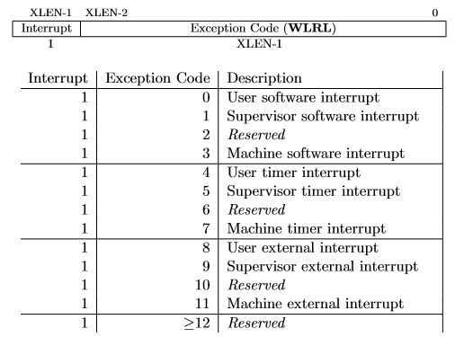
the interrupt/exception code to help identify its cause. An
exception code is stored in the first 31 bits of ucause and the
last bit indicatees whether or not it was an interrupt or an
exception. To check what type of exception/interrupt occured use
the table to the right.
These CSRs can be set by using the CSR instructions. For example, to enable
user-level interrupts in ustatus use "CSR Read/Write Immediate" instruction:
csrrwi zero, 0, 0x1. Or use pseudo-instructions to
read and write to the CSR registers. For example:
        csrr    t0, 4       # read from CSR#4 to t0
        csrw    t0, 6       # write whats in t0 to CSR#6
        csrwi   0, 0x4      # write 0x4 to CSR#0
Once an interrupt is raised it must be handled in an interrupt
handler that you will create. An interrupt handler is analogous to
a normal function but there are some key differences. An interrupt
can occur at any time, therefore the handler must guarantee that
all registers are restored to their original values after the
handler finishes. Thus, the handler must save any register that it
uses (not just the s registers) and the handler must
restore the original values to these registers prior to
returning. Also, the instruction uret must be used to
leave the interrupt handler instead of the jr ra
instruction that is used to return from a normal function.
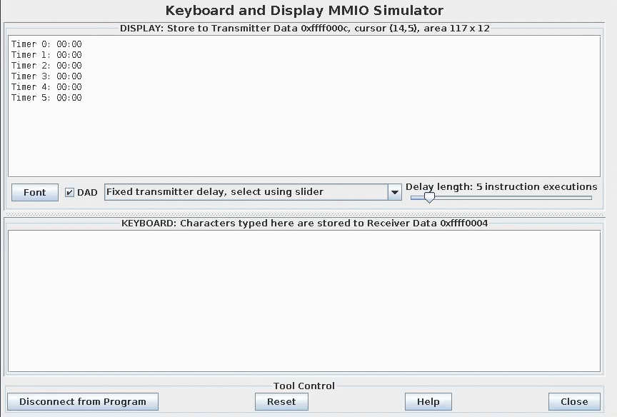
Use the Keyboard and Display MMIO Simulator, available under the "Tools" tap in RARS, to interact with the timer. You will display the timers in the display section, and will start or modify timers in the keyboard section. Don't forget to click "Connect To Program" after you assemble your program and before running it.
Generally devices have two registers associated with them, a control and a data register. The control register relays information about the device's state, and the data register relays data to or from a device.
Bit 0 in the display control register is the ready bit. Its value must be 1 before a character is sent to the display. If the ready bit is 0, you have to wait till it becomes 1 before sending a value to the data register.
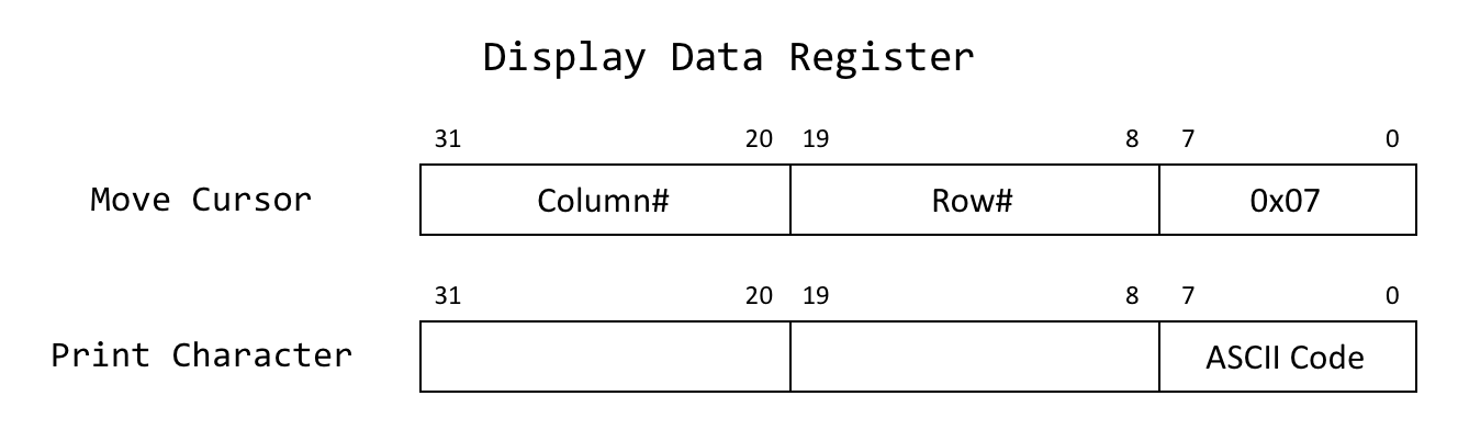
A bell character (ASCII #7) in the lower 8 bits of the data register indicates a cursor positioning command. The new position of the cursor is specified as follows: the row number is in the bits 8-19, and the column number in bits 20-31 in the data register.
To print a character, save the ASCII code for that character to the lower 8 bits of the data register, the upper 24 bits are irrelevant if the character is not the bell character.
The keyboard input, also has a control and a data register. The control register is used to enable keyboard interrupts. Setting bit 1 in the control register to 1 enables keyboard interrupts. Bit 0 is automatically reset to 0 after a keyboard interrupt occurs. Thus, after handling such an interrupt, the handler must set this bit to 1 to re-enable keyboard interrupts.
The keyboard data register contains the code of the key pressing that caused the interrupt.
A separate keyboard interrupt occurs for every key pressed when the keyboard interrupts are enabler. Therefore, the user program receives one character at a time. The solution for this lab has to build a string using these characters until it receives a newline character (ASCII code 0x0a), corresponding to the user pressing enter. At that point, the solution has to parse the string, start/modify the timer accordingly, and reset the string for the next input. For more information about the tool, click the help button in the tool window.
In RISC-V timing functionality is managed by the timing harware thread (hart), maintaining the time asynchronous and allowing the program to raise an interrupt at a specific time. To do this the core keeps track of the time in the 64-bit register time which holds the current time (in milliseconds) since the program started. To generate a timer interrupt at a specified time, the value in the register timecmp must be set. When the value in timecmp is less than or equal to the value in time a timer interrupt occurs. To simulate RISC-V timing functionality you must use the Timer Tool under the "Tools" tap in RARS. Don't forget to click "Connect To Program" and "Play" after you assemble your program and before running it.
Memory-mapped IO allows interaction with external devices through an interface pretending to be system memory. This mapping allows the processor to communicate with these devices using the load-word and store-word instructions.
The keyboard control reigister is mapped to the address
0xFFFF0000. For interrupts to be enabled, bit 1 must
be set to 1; after the keyboard interrupt occurs, this bit is
automatically reset to 0.
The keyboard data register is mapped to the address
0xFFFF0004. The ASCII value of the last key pressed
is stored here.
The display control register is mapped to the address
0xFFFF0008. Bit 0 of this register indicates whether
the processor can write tothe display. While this bit is 0 the processor cannot
writte to the display. Thus, the program must wait until this bit is 1.
The display data register is mapped to the address
0xFFFF000C. When a character is placed into this
register, given that the display control ready bit (bit 0) is 1,
that character is drawn onto the display. If the character is the
bell character (ASCII code 0x07) the display will move
the cursor and the bits 8-19 and 20-31 correspond to the row and
column respectively.
The time register is mapped to the address 0xFFFF0018.
time is a read only register holding the time since the the program
has started in milliseconds.
The timecmp register is mapped to the address 0xFFFF0020.
timecmp holds the time that the timer will go off. Writing to this register
is required in order to setup the timer.
The task in this lab is to write a program in RISC-V assembly that manages six separate countdown timers concurrently. This program will read in the time in seconds for a given timer, accurately count down the timers to zero, and then reset the timer. The program must do the following:
Timer x:
       00:00
, with the value of x varying from 0
to 5 from the top of the DISPLAY section. The
program must update all the timers every second.seconds@timer where seconds is the amount
of time, measured in seconds, that the timer should run (to a
maximum of 3599 seconds) and timer is a value from 0-5
representing one of the 6 timers that can be set.
Reading or printing syscalls cannot be used in this program. Instead, the program must use the interrupt/poll system to interact with the keyboard and the display.
You're provided with a Keyboard and Display MMIO Simulator display demo and a solution template with pre-programmed functionality that you can use.
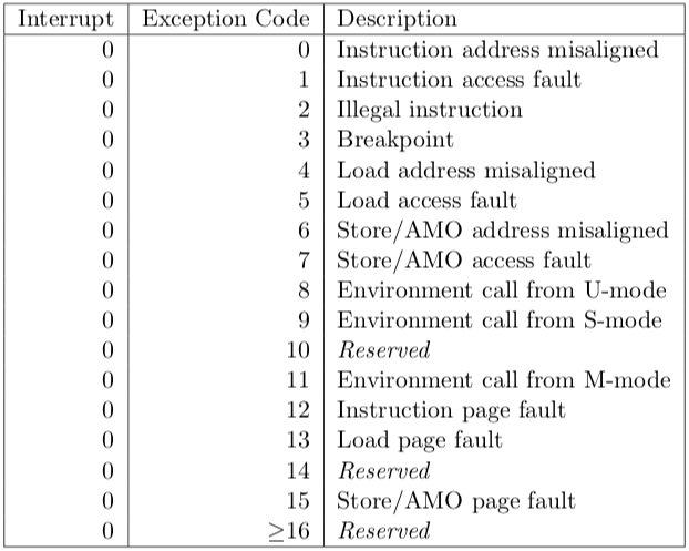
As you will be writing your own handler, runtime errors won't be shown with RARS as usual. Thus, you are provided with a section of the handler that prints the line where an error occurred and the error code. Use the table to the right to identify the error.
Slides used for in-class introduction of the lab (.ppt) (.pdf)
Slides used for in-lab introduction of the lab (.pdf)
Assignments too short to be adequately judged for code quality will be given a zero.
There is a single file to be submitted for this lab. The file name should be multiTimer.s and it should contain the code for both the interrupt handler and the main (i.e. your file must contain all the code for a successful stopwatch execution).