Typing quickly and precisely is an important skill for all university students. This lab focuses on using interruptions to create a typing game. Instead of using syscalls, we use the Memory Mapped device and timer tool on RARS. The exception handler used to manage these exceptions is created by the student.
Typing games are common games to practice and improve typing skills. The typing game in this lab is much simpler than other ones available online. Here are a few typing games to help you become familiar with the concept.
The typing game in this lab receives an array of phrases. The level of play --- easy, medium, and hard --- must be selected before the game begins. The level determines the amount of starting time as well as the bonus time awarded after completing a sentence the player is given to type. The player will have to type the exact phrase that is displayed on the screen as quickly as possible.
The goal of this lab is for students to become familiar with the concepts of interruptions and exceptions, and to gain practical experience programming an exception handler in RISC-V.
In this typing game the player starts with an initial time budget to type. When the time is up, the game is over. Whenever the player finishes typing a complete sentence, they are awarded bonus time.
The game has three levels and both the initial time budget and the bonus time are determined by the level selected at the start of the game. In this lab the following times should be used:
| Game Level | Initial Time Budget | Bonus Time |
|---|---|---|
| 1 | 60 | 12 |
| 2 | 30 | 6 |
| 3 | 20 | 4 |
To create this simple typing game in RISC-V, write a program that reads commands from the keyboard input, handles timer interrupts and manages the display output. The typing game uses two screens for display. One screen is displayed after the other. After the start screen, there will be the game screen.
1 2 or 3 is recognized. There is no need
for the player to type enter. Once your program recongizes one
of the three numbers the game begins. a0 contains the
first element of the array. At the start, display a
* character under the first character of the
phrase to be typed to start the progress bar. Whenever the
player types the correct character, add a *
character to the progress bar. At the end of the phrase, clear
both the phrase and the progress bar characters and display a
new phrase. This screen also displays the number of points and
the remaining time that the player has to play. 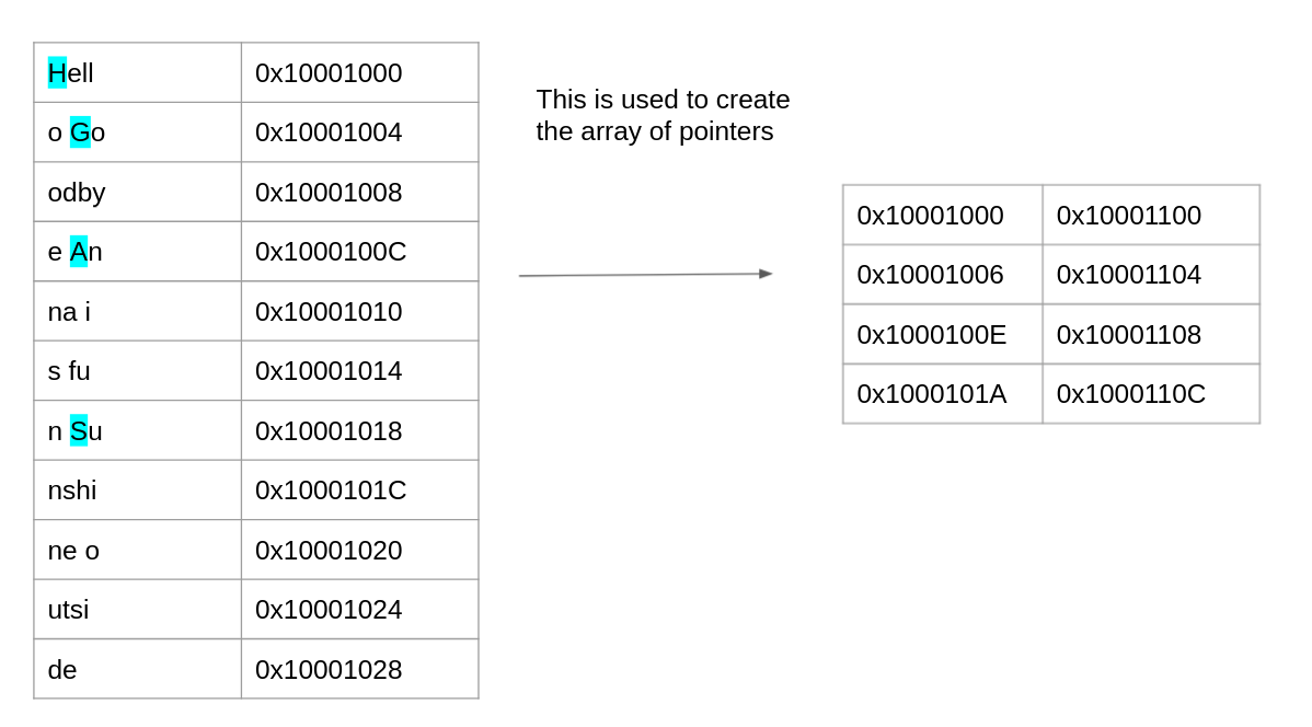
This visually shows how the phrases for the typing game are stored in memory. All of the phrases are placed in memory. An another array of pointers is created. Each points to the first letter of phrase, the letters highlighed in blue.
There are two inputs to the game, both provided by interruptions:
Keyboard and Display MMIO Simulator.
Once a character is recognized, it needs to be
displayed. If the character matches the next character
in the sentence, then another * character
will be added to the progress bar. 
This lab uses external interrupts from hardware. The role of four CSRs (Control and Status Registers) are important for the use of interrupts:
ustatus (User Status Register, CSR#0) is a 32-bit
register that controls and manages user-level interrupts in the hardware thread
(hart). To enable user-level interrupts set the 0th bit of this register
to 1.uie (User-Interrupt Enable Register, CSR#4) is a 32-bit
register that controls the types of interrupts that are enabled using a bitmask.
Bits 4 and 8 are relevant for this lab. The 4th enables user-level timer interrupts.
The 8th bit enables user-level external interrupts. These bits must be set to 1 to
enable interrupts from the timer and the keyboard.utvec (User Trap-Vector Base-Address Register, CSR#5)
is a 32-bit register that controls where interrupts are handled. The register
holds the address of the interrupt handler that should be called when an interrupt
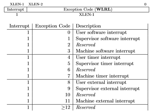
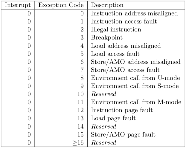
or exception occurs.ucause (User Trap Cause Register, CSR#66) is a 32-bit
register that identifiies which type of interrupt is being handled. After an exception or
an interrupt, this register holds the interrupt/exception code to help identify
its cause. An exception code is stored in the first 31 bits of ucause and the
last bit indicates whether or not it was an interrupt or an exception. To
check what type of exception/interrupt occurred refer to the table. These CSRs can be set by using the CSR instructions. For example, to enable
user-level interrupts in ustatus use "CSR Read/Write Immediate"
instruction: csrrwi zero, 0, 0x1. Or use pseudo-instructions to read
and write to the CSR registers. For example:
    csrr    t0, 4   # read from CSR#4 to t0

    csrw    t0, 6   # write whats in t0 to CSR#6

    csrwi   0, 0x4 # write 0x4 to CSR#0
Once an interrupt is raised it must be handled in the interrupt
handler created in this assignment. An interrupt handler is
analogous to a normal function but there are some key
differences. An interrupt can occur at any time, therefore the
handler must guarantee that all registers are restored to their
original values after the handler finishes. Thus, the handler must
save any register that it uses (not just the s
registers) and the handler must restore the original values to
these registers before returning. Also, the instruction
uret must be used to leave the interrupt handler
instead of the jr ra instruction that is used to
return from a normal function. Again, a student should not call functions exterior to the handler if they are using the user stack point.
Use the Keyboard and Display MMIO Simulator, available under the
"Tools" menu in RARS, to interact with the simulator . Display the
simulator in the display section, and input commands in the keyboard
section. Don't forget to click "Connect To Program" after assembling the program
and before running it.
Generally, devices have two registers associated with them, a control, and a data register. The control register relays information about the device's state, and the data register relays data to or from a device. A description of the control and data registers for the keyboard and display can be found in the Memory-Mapped IO section.
A separate keyboard interrupt occurs for every key pressed when the keyboard interrupts are enabled. Therefore, the user program receives one character at a time.
In RISC-V, timing functionality is managed by the timing hardware thread
, maintaining the time asynchronously and allowing the program to raise
an interrupt at a specific time. To do this the core keeps track of the time in
the 64-bit register time which holds the current time (in milliseconds)
since the program started. To generate a timer interrupt at a specified time,
the value in the register timecmp must be set. Each time the timecmp
register is used, the student must reset the timecmp register with the new time
each time . A description of the
time and timecmp registers can be found in the
Memory-Mapped IO section. To simulate RISC-V timing functionality
use the Timer Tool under the "Tools" menu in RARS. Don't forget
to click "Connect To Program" and "Play" after assembling the program and before
running it each time you run the program.
Memory-mapped IO allows interaction with external devices through an interface pretending to be system memory. This mapping allows the processor to communicate with these devices using the load-word and store-word instructions. Here are the memory mappings and descriptions of important I/O registers for this lab:
| Register | Memory Address | Description |
|---|---|---|
| Keyboard control | 0xFFFF0000 |
For keyboard interrupts to be enabled, bit 1 of this register must be set to 1; after the keyboard interrupt occurs, this bit is automatically reset to 0. |
| Keyboard data | 0xFFFF0004 |
The ASCII value of the last key pressed is stored here. |
| Display control | 0xFFFF0008 |
Bit 0 of this register indicates whether the processor can write to the display. While this bit is 0 the processor cannot write to the display. Thus, the program must wait until this bit is 1. |
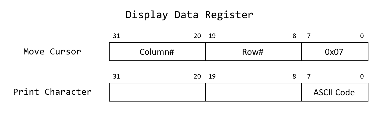
| Display data | 0xFFFF000C |
When a character is placed into this register, given that the display control
ready bit (bit 0) is 1, that character is drawn onto the display. If the
character is the bell character (ASCII code 0x07) the display will
move the cursor and the bits 8-19 and 20-31 correspond to the row and column
respectively. View the image. |
| Time | 0xFFFF0018 |
This is a read-only register that holds the time since the program has started in milliseconds. |
| Timecmp | 0xFFFF0020 |
When the value in this register is less than or equal to the value in
time a timer interrupt occurs. Writing to this register is
required to set up a timer. |
A solution to this lab must generate random numbers to determine which phrase of the array is displayed for the player
Implement a Linear Congruential Generator (LCG). An LCG is a simple pseudorandom number generator (PRNG) algorithm defined as the recurrence relation:
Xi = ( aXi-1 + c ) % m
Where X0, a, c,
and m are constants. X0 is
the seed value, a is the multiplier, c
is the increment, and m is the modulus.
The first randomly generated number is
X1, the second is
X2, and so on.
With a PRNG, the sequence of generated numbers is always the
same for the same values of X0, a,
c, m. This consistency will be important for debugging the solution to this lab.
Here is a useful tool
for that generates a random sequence of numbers based on values of
X0, a, c, m that
can be used to test the program. To learn more about linear
congruential generators, view
this page.
Reading or printing syscalls cannot be used in this program. Instead, the program must use the interrupt/poll system to interact with the keyboard and the display.
When executing RARS with your own handler, runtime errors won't be shown in RARS as usual. Thus, a section of the handler that prints the line where an error occurred and the error code is provided. Use the table to the right to identify the error.
Make sure the handler does not call any functions. This ensures proper grading through the scripts and makes it easier to debug the code.
There are two phases in the execution of the game: reading the level of the game; and playing the game. Each of these phases can execute in a loop that changes the state of the display when there is an interruption caused either by the input of a command or by a timer. A possible design would be to reprint the display for every iteration of the loop. However, such a design could produce a flickering in the screen in certain types of monitors. Therefore a better design is to have flags that indicate when an action must be taken in the loop. For instance, the display only needs to be reprinted when its content has changed. Therefore the loop can simply check on specific flags and only take action when action is needed. Flags are variables that can store either 0 or 1. You can use flags to determine what should happen on the next iteration of the loop. By using different flags for the separate tasks of the program, you can ensure that you only execute tasks when needed.
The exit conditions for the loops are as follows. The
game-level screen loop exits once a valid input is received. The
typing-screen loop exits once the timer has run down to zero
seconds. At that point you can simply end the game by returning
from the typing function.
Here is an example of how you can use a flag to determine when a program prints its output:
changed) that contains the value:0, if the output has not changed since
it was last printed and thus doesn't need to be printed. 1, if the output has changed
since it was last printed and thus should be
printed.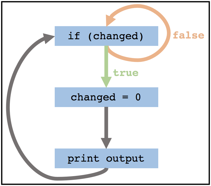
Using flags in the loop also separates the code into tasks making it easier to understand and debug.
The following lines appear in the .data section of
common.s:
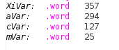
This is similar to defining four global variables. These
variables are used in the linear congruential generator and
should contain the values Xi,
a, c, and m
respectively. These variables must be used in the
random function so that the solution works with
grading scripts. For testing, initialize the first three values
to any value, but keep mVar as 25.
You may add any other global variables that could be used to help run your program.
When an interrupt is raised, the program is paused and execution is transferred to
the interrupt handler. To ensure that the program can safely resume execution after
returning from the handler, the registers used by the handler must be saved upon
entering the interrupt handler and restored before returning. The registers cannot be
saved using the stack pointer because the stack pointer may be corrupted. Therefore, in
common.s we have allocated memory labeled iTrapData where
your handler may save registers. In common.s we have also placed the
address of iTrapData into the control status register #64,
uscratch. You can use uscratch and the CSR instruction
csrrw to save and restore all the values of registers used in the
handler.
After returning from the handler, all registers must have the same value as when the
program paused and uscratch should contain the address of the
iTrapData. The first instruction executed in the handler and the last
instruction executed before returning from the handler should be
csrrw a0, 0x040, a0, where a0 is chosen by convention.
Here is some sample code that saves two registers and a0 in the
interrupt trap data:
      handler:

      # swap a0 and uscratch
      csrrw   a0, 0x040, a0     # a0 <- Addr[iTrapData], uscratch <- PROGRAMa0

      # save all used registers except a0
      sw      t0, 0(a0)         # save PROGRAMt0
      sw      s0, 4(a0)         # save PROGRAMs0

      # save a0
      csrr    t0, 0x040         # t0 <- PROGRAMa0
      sw      t0, 8(a0)         # save PROGRAMa0

      ...
Non-re-entrant handler: It is up to you how you manage the memory allocated for iTrapData.
If you allocate a specific address to save a given register --- for example, register s0 is always saved in Addr[iTrapData]+4 --- then your handler is not re-entrant.
You cannot enable interruptions while you are handling an interruption because doing so could cause the first value of s0 that you had saved to be overwritten.
Re-entrant handler: An elegant solution to create a re-entrant handler is to implement a stack in the memory area reserved for iTrapData.
The solution would have to handle an interrupt stack pointer. It would have to ensure that space is allocated in this stack for a new interruption frame
before interruptions are re-enabled. Once space is reserved in the interrupt stack to save the registers that the handler will use, then interrupts can safely be re-enabled. In this case we have a re-entrant handler.
It would be difficult to create a set of tests to determine if a handler is re-entrant. Therefore, in this lab we do not require the implementation of a re-entrant handler. It is acceptable to keep interruptions disabled while an interruption is being processed.
Write assembly code for the following functions in the file named typing.s
typing:
handler:
handlerTerminate
is provided. It should catch interrupts/exceptions unhandled by the student handler, terminating the program and
providing debugging messages
jal ra, handler. Instead the address of the handler should be stored in the utvec control status
register (CSR #5) at the start of the program. When an interrupt
is raised, the execution of the program jumps to the instruction address stored in utvec random:a0: a pseudorandom number, Xi, between
0 and 24Xi from
Xi-1, a, c, and
m. Replace Xi-1 in memory with the newly
generated Xi.
XiVar, aVar, cVar, and
mVar from the data section of
common.s (see the subsection Global Variables in the Constraints section for information on
these variables). Before returning, the generated number
Xi must be stored in
XiVar. It should be possible to call
random multiple times, back-to-back. Therefore
any needed state update to the global variables must be
performed in the function.The functions below are optional suggestions. These are not required and will not be tested when grading this assignment. These function specifications are provided to help you understand the different modular parts of this assignment. This can help with the debugging process. Students are free to add any other functions that help them create their solution.
printDisplay (optional)
intToStr (optional)
newPhrase (optional)
Write additional functions as needed. Code from the
materials provided in this course can be used in the solution as
long as the source is acknowledged. For example,
displayDemo.s in Code/Demo/ may be helpful
for printing to the Keyboard and Display MMIO Simulator
display.
mVar value to be the number of phrases in
your file. This ensures that your random number generator
correctly generates numbers within the correct range. common.s file looks for all of the newline
characters to determine phrase breaks.Assignments too short to be adequately judged for code quality will be given a zero.
There is a single file to be submitted for this lab:
typing.s should contain the code for both the interrupt handler
and the function typing.
main label to this file.include "common.s"Code folder of the git repository