CMPUT 229 - Computer Organization and Architecture I
Lab 3: Fractal
Creator: Nathan Ulmer
DISCLAIMER: This page contains math equations and images. If you cannot see either of them on this page, try loading the page on a different web browser.
Introduction
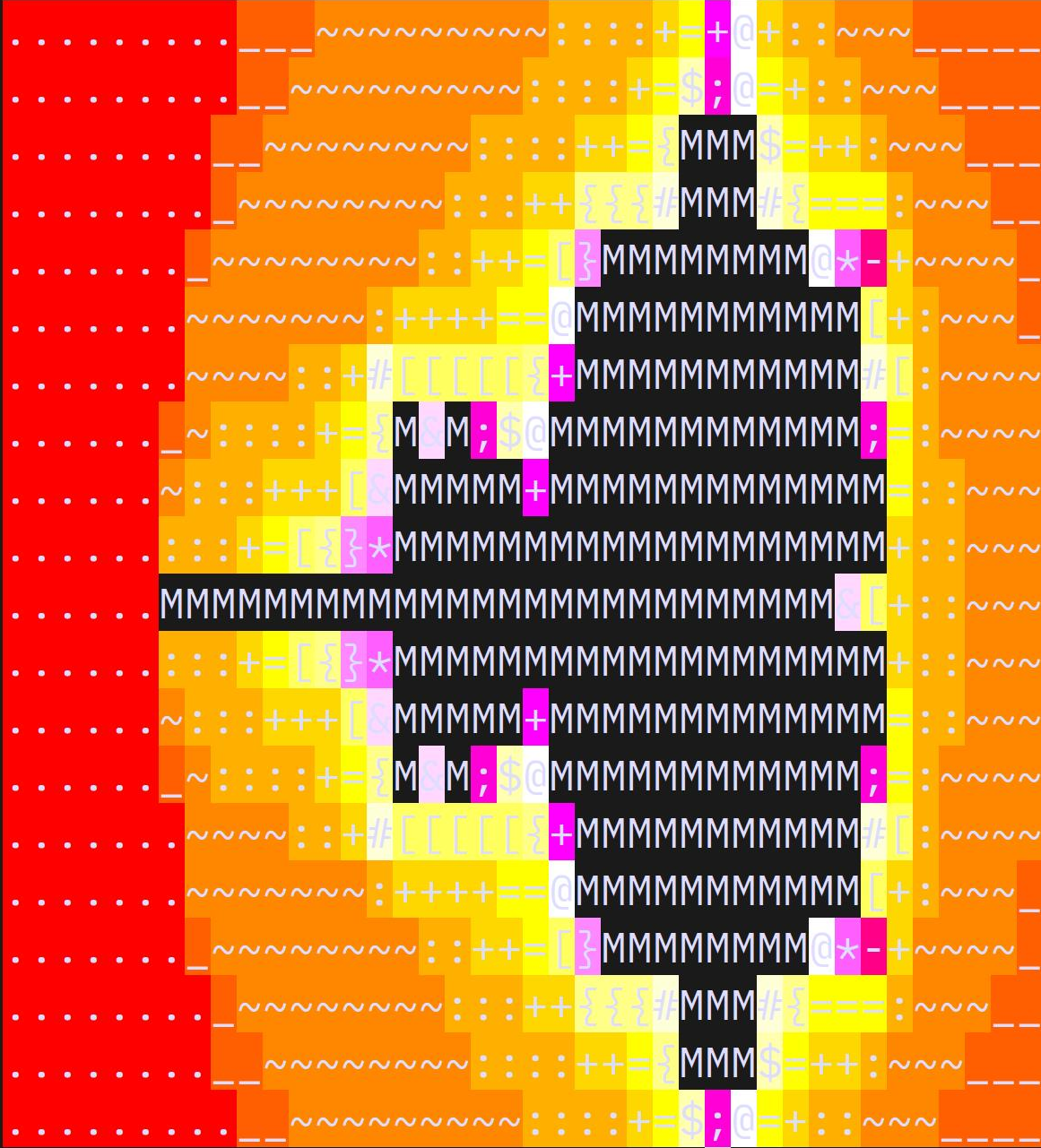
In this lab you will learn to use the floating-point capabilities of the RISC-V architecture to render a portion of the Mandelbrot fractal. You will use a RISC-V library called GLIR, developed by former 229 students at the University of Alberta, to render the results to the terminal. The following image is an example output from a solution to this lab:
The Mandelbrot Fractal
Complex Numbers
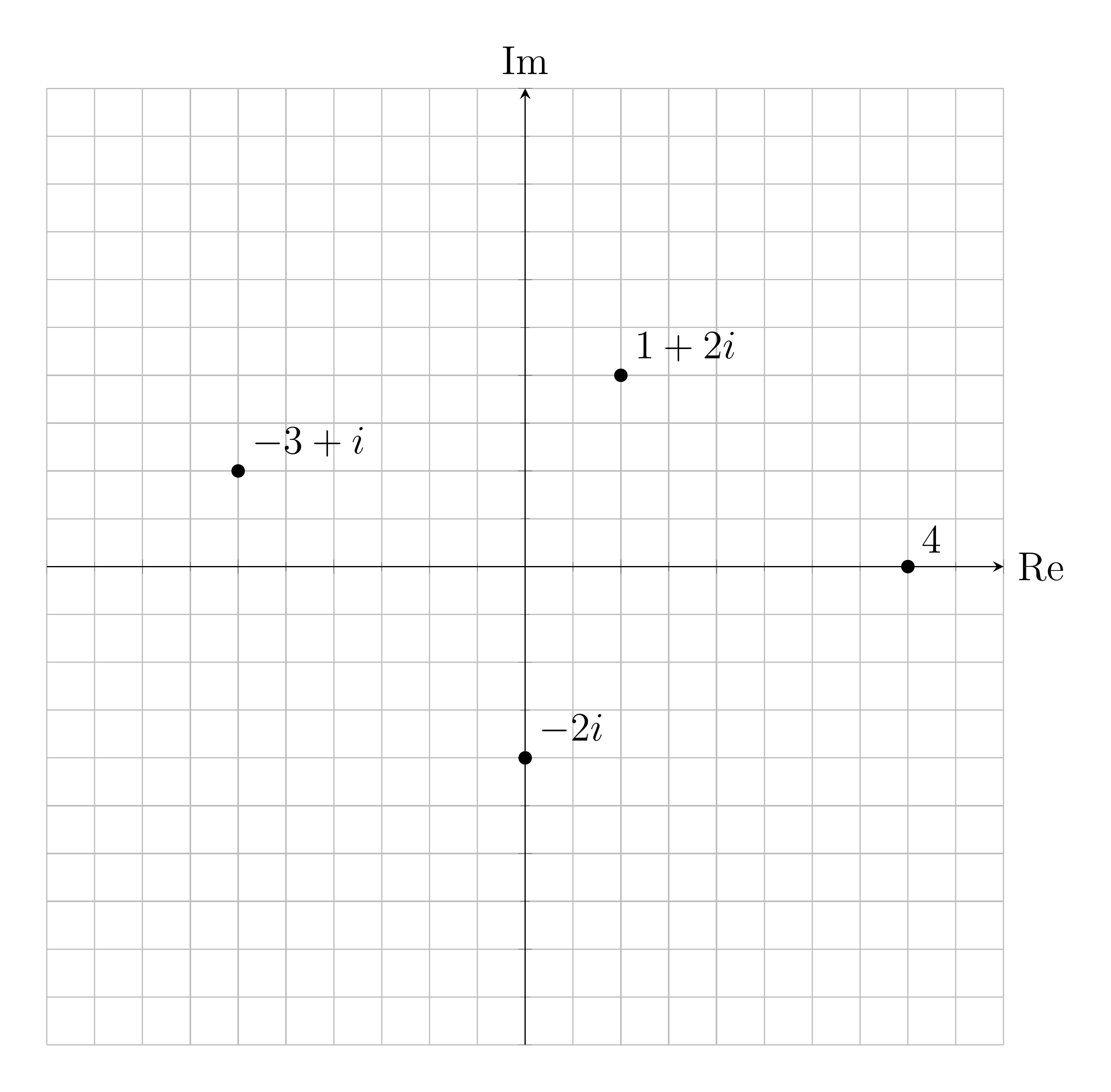
A complex number contains two parts: a real part and an imaginary part. For example \(1 + 2i\) is a complex number with a real part of \(1\) and an imaginary part of \(2\). The object \(i\) is a special value known as the imaginary unit, and it satisfies the equation \(i^2 = -1\). Expressions involving complex numbers follow the same standard arithmetic rules as real numbers, provided that you treat \(i\) as a variable and \(i^2\) as \(-1\). It is natural to visualize complex numbers on a two-dimensional plane, called the complex plane instead of the one-dimensional number line used to visualize real numbers.
The absolute value, also called the magnitude, of a complex number is the distance between the origin and the point defined by the real and imaginary values of the number in the complex plane. The magnitude of some complex number \(z = a + bi\) is \(|z| = \sqrt{a^2+b^2}\).
Mandelbrot Set
The Mandelbrot set is a set of complex numbers defined by the following recursive function: \[ \begin{eqnarray} z_0 &=& c \\ z_n &=& z_{n-1}^2 + c\\ \end{eqnarray} \] A complex number \(c\) belongs to the Mandelbrot set if the value of this function does not tend to infinity when \(n \to \infty\). It is known that no complex number \(z\) such that \(|z| \ge 2\) belongs to the Mandelbrot set. Therefore, whenever the recursion above reaches a value \(|z| \ge 2\) the algorithm can conclude that the initial value does not belong to the set.
We can render the Mandelbrot set by mapping a portion of the complex plane to a displaying device. For example, the complex number \(23 + 4i\) could be located \(23\) steps to the right of the origin, and \(4\) steps above the origin. The following image colours all the numbers that belong to the Mandelbrot set in black and the numbers that do not belong to the set in white. On the axis, numbers that belong to the Mandelbrot set are coloured in white, and the numbers that don't belong in black.

Mandelbrot Animations
Artists are interested in the complex numbers that do not belong to the set. More specifically, they are interested in the value of \(n\) for which the value of \(z_n\) has reached a value that is known to escape to infinity. The value of \(n\), also referred to as the escape time, is used to the colour the portions of the plane that do not belong to the set.
As an example, the following animation was rendered using a solution to this assignment. The following process was used to create the animation:
- First frame (red section): The maximum iteration parameter was set to \(1\). This section represents complex numbers for which \(|z_0| \ge 2\).
- Second frame (dark orange section): The maximum iteration parameter was increased to \(2\). This section represents complex numbers where \(|z_0| < 2\) but \(|z_1| \ge 2\).
This process continues. As the maximum number of iterations increases, more and more points escape. For this animation the maximum number of iterations was increased from \(1\) to \(21\). For high resolution animations, trillions of iterations must be computed to find out if a given complex number escapes. Creating such animations is not a requirement for this lab.
Escape Time Algorithm
Given an initial point \(c\) on the complex plane with real part x_0
and imaginary part y_0 the escape time can be calculated using the
following algorithm:
x = x_0
y = y_0

iter = 0

while (x*x + y*y < 4 and iter < max_iter) {
    temp = x*x - y*y + x_0
    y = 2*x*y + y_0
    x = temp
    iter += 1
}
Where max_iter is the maximum iteration count.
After this loop has completed, the iter variable contains the
escape time.
GLIR - Graphics Library for RISC-V
The graphical output of this assignment will be handled with GLIR, a Graphics Library for RISC-V built at the University of Alberta. GLIR is a collection of subroutines to emulate graphics in a terminal. GLIR works by printing cells onto the terminal window. Each cell can contain any printable character and can have a background and foreground colour.
Required GLIR Functions
This lab only uses the GLIR_PrintString and
GLIR_SetColor functions.
GLIR_PrintString
  Prints the specified null-terminated string starting at the given location.

  Arguments:
    a0: Address of the string to print
    a1: Integer value 0-999, row to print to
    a2: Integer value 0-999, column to print to

  Returns:
    N/A
GLIR_SetColor
  Sets the colour of the text to the colour specified.

  Arguments:
    a0: Colour code
    a1: 0 if setting background, 1 if setting foreground

  Returns:
    N/A
Coordinate Systems
This lab uses two coordinate systems. The coordinate system for the Mandelbrot fractal is the complex plane. The terminal uses a separate set of integer coordinates to refer to particular cells. You have to translate from the Mandelbrot coordinates to the terminal coordinates to render the fractal.
Mandelbrot Coordinates
A representation of a rectangular subset of the complex plane uses two
intervals: one for the range of real values, and another for the range of
imaginary values.
A region is defined by a pair of intervals representing the real and imaginary number ranges:
([min_r, max_r], [min_i, max_i])
For example the region ([-3, 4], [-2, 1]) appears as follows:

Terminal Coordinates
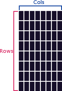 The terminal window is made up of cells.
Each cell has an integer coordinate
The terminal window is made up of cells.
Each cell has an integer coordinate (row, col).
For example, consider the following \(8\times 8\) terminal window:
The terminal spans [0, # of rows] in the vertical position
and [0, # of columns] in the horizontal position.
The row position represents the vertical
distance from the top of the screen.
The column position represents
the horizontal distance from the left side of the screen.
This is a standard terminal coordinate system that is preserved by GLIR
because it is a common graphics standard, despite being opposite of the
mathematical standard to put the horizontal element first in a coordinate.
Translation
An input file, parsed at the start of the program, specifies the dimensions of
the terminal window and the intervals for the complex coordinate system.
In this lab, each cell is represented by the point at its top left corner.
You must compute the location of a particular cell in the complex plane using
the step sizes computed by getStep.
The figure below illustrates the mapping for a display with \(6\times 8\) cells
to display the section of the complex plane defined by
([-2.5, 1], [-1, 1]).
The step_r and step_i denote the real and
imaginary step sizes, respectively.
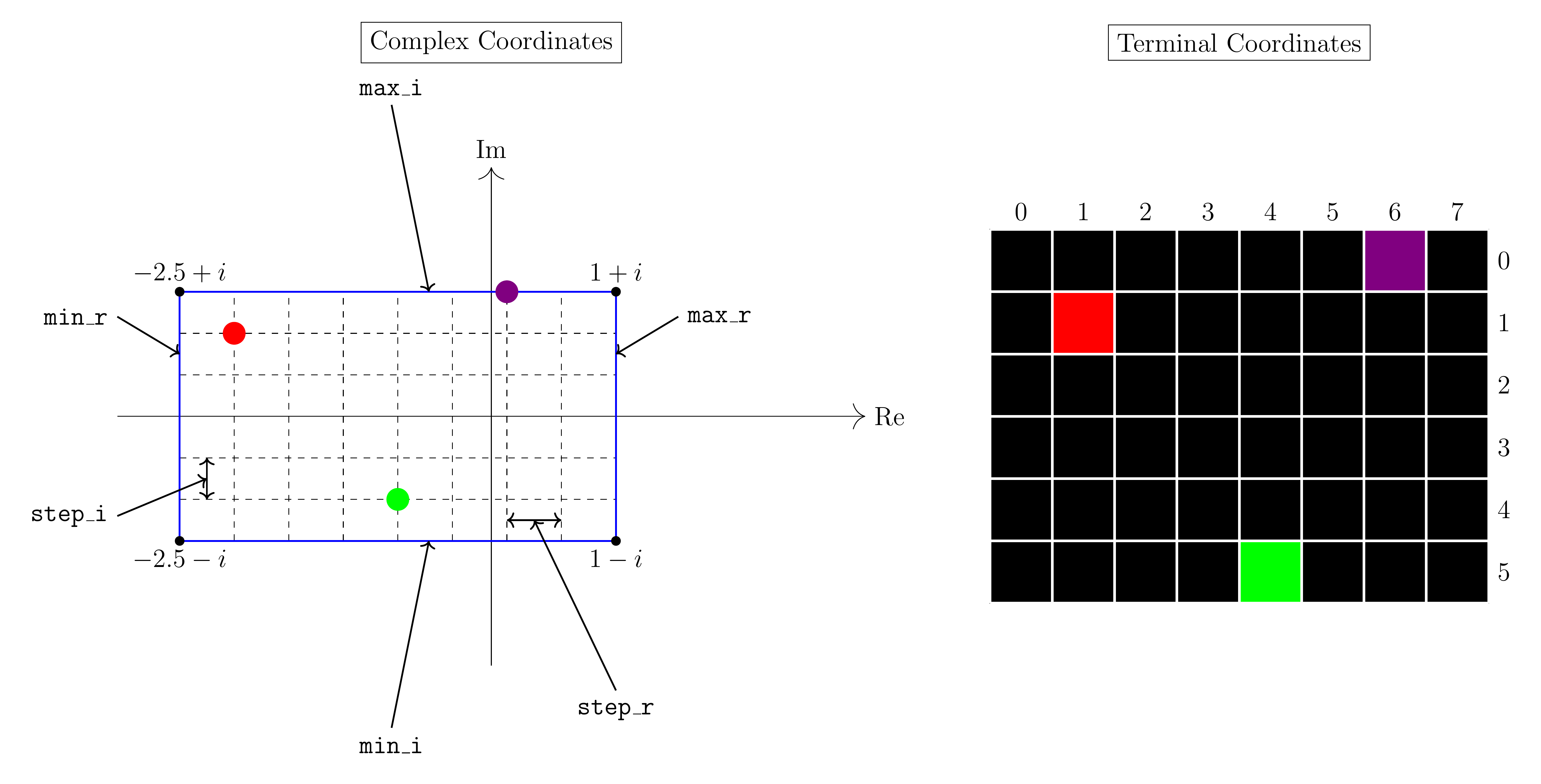
The red point on the complex plane is \(−2.0625 + \frac{2}{3}i\) and it maps to the point \((1, 1)\) on the terminal. The green point on the complex plane is \(−0.75 - \frac{2}{3}i\) which maps to the point \((5, 4)\) on the terminal. Finally, the purple point on the complex plane is \(0.125 + i\) which maps to \((0, 6)\) on the terminal.
In the following animation the terminal dimensions remained constant, but the portion of the complex plane that is rendered varies. To generate this animation, the solution progressively renders smaller and smaller portions of the plane, focusing in on a small region in the left portion of the original image. Your solution is not required to create animations.
Rendering the Fractal
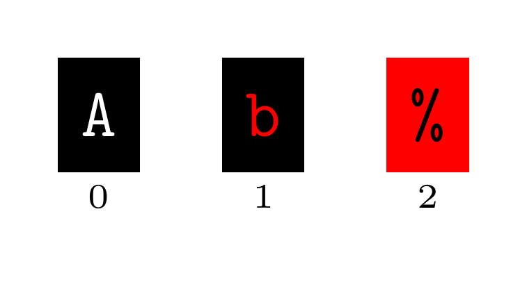
The terminal is composed of a grid of cells.
Each cell has a foreground colour, a background colour, and a character.
In the following graphic, the foreground of cell 0 is white, the background is
black, and the character is an A.
The foreground colour of cell 1 is red, the background is black, and the
character is b.
Finally, the foreground colour of cell 2 is black, the background is red, and
the character is %.
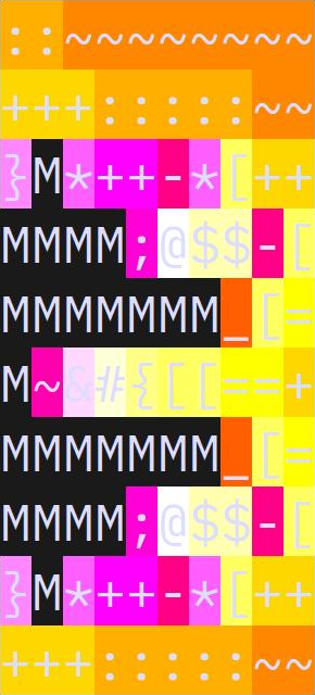
Your solution will draw the Mandelbrot set using the background colour and the character of each cell in the terminal. The foreground colour is not modified. If a cell in the terminal has a corresponding point in the complex plane \(c\), then that cell in the terminal is drawn according to the following rules:
-
If \(c\) doesn't escape, then \(c\) is "in" the mandelbrot set.
The cell in the terminal is drawn using a black background and
the
Mcharacter. - If \(c\) escapes, then the background colour and character are selected from an array using the escape time. The selection process is described later in this section.
In the following graphic, points on the middle left failed to escape and are
drawn with a black background and M character.
In the remainder of the image, the points have differing escape times, and
thus have different background colours and characters.
All cells have the same foreground colour.
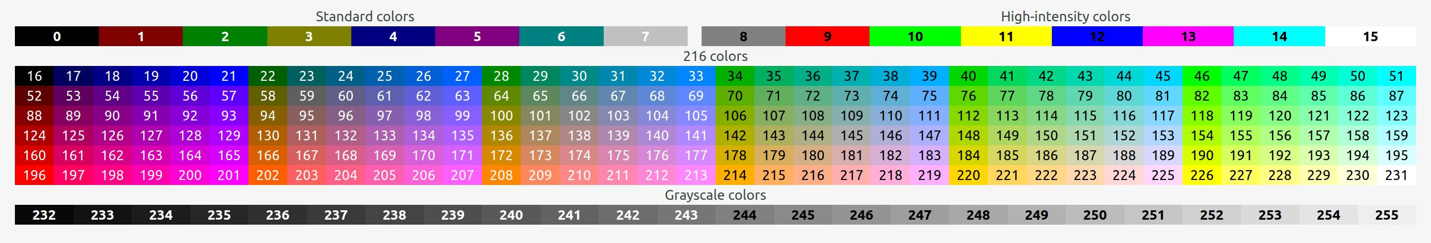
Colours
GLIR uses ANSI escape codes, which are a set of character sequences that can be used to modify the text of the terminal. GLIR abstracts away the details of ANSI escape codes and allows the user to select the desired colour from a lookup table:
Included in the common.s file are the following variables:
-
in_color: Byte containing the colour code for black. -
palette: Array of bytes, each byte contains a single colour code. -
palette_size: The number of elements in thepalettearray.
The colours in palette are used for the backgrounds of points
that escape.
A palette that contains 5 colours would have the following layout
in memory:
| Address | 0x10001000 |
0x10001001 |
0x10001002 |
0x10001003 |
0x10001004 |
|---|---|---|---|---|---|
| Value | 196 | 202 | 214 | 220 | 226 |
Characters
Similarly to the colours, the common.s file contains the
following variables for characters:
-
in_symbol: The string"M". -
symbols: An array of sequential single character strings. Each string is two bytes: the first byte is the character, and the second byte is the null-terminator. -
symbol_size: The number of elements in thesymbolsarray.
The strings in symbols are used to render the characters of
points that escape.
If symbols was composed of the following
characters ._~:+, then symbols would have the
following layout in memory:
| Address | 0x10001000 |
0x10001001 |
0x10001002 |
0x10001003 |
0x10001004 |
|---|---|---|---|---|---|
| Value | '.' |
'\0' |
'_' |
'\0' |
'~' |
| Address | 0x10001005 |
0x10001006 |
0x10001007 |
0x10001008 |
0x10001009 |
| Value | '\0' |
':' |
'\0' |
'+' |
'\0' |
Selecting the Background Colour and Character
To render the fractal, first compute the escape time of the corresponding
complex number.
If the point doesn't escape before the maximum number of iterations has been
reached, draw the cell using in_color and in_symbol.
If the point escapes, the background colour and character are selected
from palette and symbols, respectively.
To select the background colour compute index = escape_time %
palette_size, then use the index'th colour
from palette.
Similarly, to select the character, compute index = escape_time %
symbol_size, then use the index'th string
from symbols.
Floating Point
The RISC-V architecture adds support for floating-point through the "F", "D", and "Q" extensions. In this lab, we are concerned with the "D" extension which adds support for 64-bit (double) floating-point. This extension includes an entirely separate set of floating point registers, along with new instructions for operating on these registers. This lab does not require an understanding of binary floating point representations — FP representations will be covered later in CMPUT 229.
Integer and Floating Point Registers
RISC-V has regular registers (e.g. a0 or t6) that
hold integer values.
The "D" floating-point extension adds 32 additional floating-point registers,
each of which can hold a 64-bit float.
In the following lists we will
denote rd, rs1, and rs2 as the integer
destination and source registers.
Similarly fd, fs1, and fs2 will denote
the floating-point destination and source registers.
Conversion
The following instructions convert to and from floating-point numbers and integers. Pay careful attention to which registers are integer registers, and which are floating-point.
-
fcvt.d.w fd, rs1-
Convert the value in
rs1to a 64-bit floating-point number and store the result infd.
-
Convert the value in
-
fcvt.w.d rd, fs1-
Convert the value in
fs1to a 32-bit signed integer and store the result inrd.
-
Convert the value in
Arithmetic
The following instructions perform floating-point arithmetic in floating-point registers.
-
fadd.d fd, fs1, fs2fd <- fs1 + fs2
-
fsub.d fd, fs1, fs2fd <- fs1 - fs2
-
fmul.d fd, fs1, fs2fd <- fs1 * fs2
-
fdiv.d fd, fs1, fs2fd <- fs1 / fs2
Control
RISC-V does not include instructions to branch directly on floating-point conditions. Instead, there are comparison instructions which set integer registers based on floating-point conditions.
-
feq.d rd, fs1, fs2rd <- (fs1 == fs2) ? 1 : 0
-
flt.d rd, fs1, fs2rd <- (fs1 < fs2) ? 1 : 0
-
fle.d rd, fs1, fs2rd <- (fs1 <= fs2) ? 1 : 0
After executing one of these instructions, use regular RISC-V branch instructions based on the value of the rd register.
Data Movement
RISC-V includes instructions to move floating-point values in and out of memory, as well as between registers.
-
fmv.d fd, fs1-
Copy the value in
fs1tofd.
-
Copy the value in
-
fld fd, X(rs1)-
Load into
fdthe value in memory atrs1 + X.
-
Load into
-
fsd fd, X(rs1)-
Store into memory at
rs1 + Xthe value infd.
-
Store into memory at
Calling Convention
Similar to the RISC-V integer registers, floating-point registers are logically partitioned into temporary, saved, and argument groups. The following table shows the calling convention for RISC-V registers:
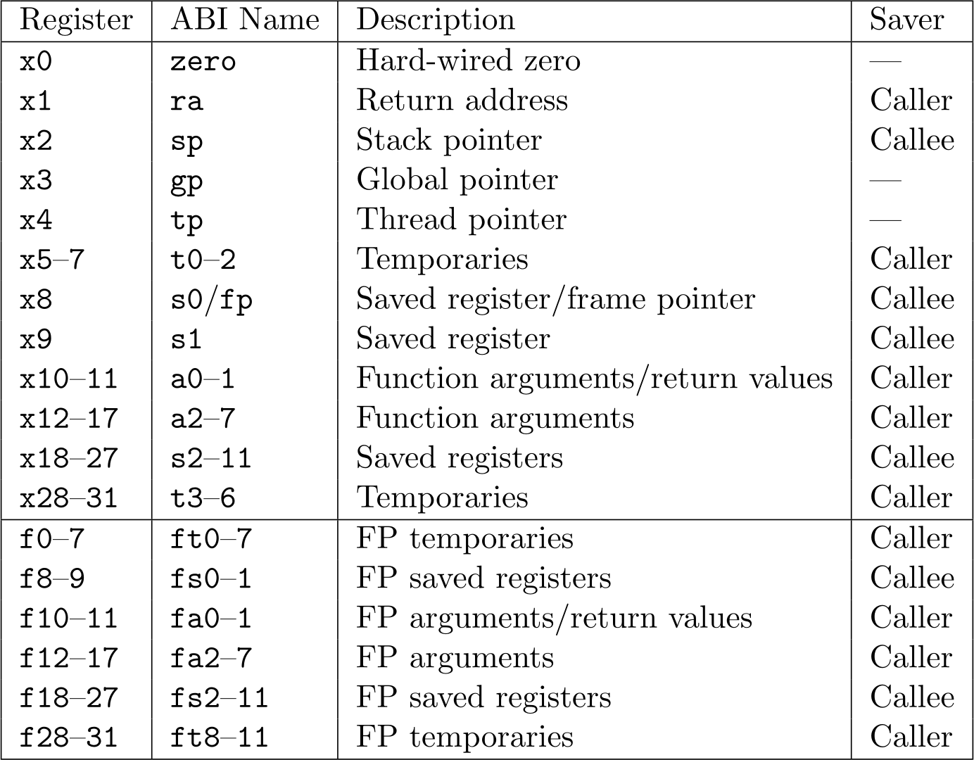
You must follow all the RISC-V calling convention for all integer and floating-point registers.
Example Floating Point Code
We have provided some sample RISC-V programs to demonstrate the use of
floating-point instructions.
These programs can be found in the Code/Examples directory.
Assignment
This lab implements a series of functions to render the Mandelbrot fractal. You are required to implement all of the following functions:
renderFractal
  This function renders a portion Mandelbrot fractal using the given parameters.

  Arguments:
    a0: Number of rows in the terminal
    a1: Number of columns in the terminal
    a2: Maximum number of iterations
    fa0: Max i
    fa1: Min i
    fa2: Max r
    fa3: Min r

  Returns:
    N/A
Refer to the render section for specific instructions on how to draw each cell.
calculateEscape
  Calculate the escape time up to a maximum number for single complex number c.

  Arguments:
    a0: Maximum number of iterations
    fa0: Re(c)
    fa1: Im(c)

  Returns:
    a0: 1 if c escaped before max iterations, 0 otherwise
    a1: Number of iterations before escape. If the maximum number of iterations
        was reached, this should be the maximum number of iterations.
Refer to provided pseudo-code to implement the escape time algorithm.
getStep
  Compute the real and imaginary step size. The step size must always be
  positive.

  Arguments:
    a0: Number of rows in the terminal
    a1: Number of columns in the terminal
    fa0: Max i
    fa1: Min i
    fa2: Max r
    fa3: Min r

  Returns:
    fa0: Real step size
    fa1: Imaginary step size
Refer to the Translation section for a definition of the step sizes.
Writing a Solution
The assembler directive .include "common.s" at the start
of the solution file causes the assembler to insert the code present in
the common.s file at the start of the solution.
The code in the common.s file reads the program arguments and
loads the corresponding file.
Read and understand the code in common.s so that you grasp how the whole program works.
The file is then parsed and given to renderFractal as input.
The code in common.s serves as the entry point, and takes care of
calling renderFractal with the correct arguments.
The code also handles the setup and tear-down of the GLIR library.
Be sure to follow the RISC-V register calling conventions for all functions in
your solution.
Integer arguments to functions should be passed in the a0-a7,
while floating-point arguments should be passed in the fa0-fa7
registers.
Integer and floating-point return values should also be passed in their
respective registers.
Testing your Lab
We have provided a small number of tests to you, located in
the Tests/ directory of your repository.
The tests provided to you are not extensive, you must create your own tests to
ensure that your solution is correct.
The solutions to the test files are given in the *.out files, and
can be viewed by running cat test.out.
Note that the binary content of the solution files may be different than what
your solution produces.
This is okay, provided your solution produces output that is visually
identical.
The format of the test input (*.txt) files is as follows:
[# of rows]
[# of columns]
[max_i]
[min_i]
[max_r]
[min_r]
[maximum iterations]
To run a test, give the test file a program arguments to RARS.
This must be done in the terminal.
For example, the following invocation runs the test
in Tests/small.txt:
rars fractal.s nc pa Tests/small.txt
The nc flag is required to prevent RARS from printing the
copyright notice, which interferes with the visual output.
Check My Lab
This lab is supported
in CheckMyLab.
To get started, navigate to the Fractal lab in CheckMyLab found in the
dashboard.
From there, students can upload test cases in the My test cases table.
Test cases are text files which follow the format described above.
Additionally, students can upload their fractal.s file in
the My solutions table, which will then be tested against all other
valid test cases.
CheckMyLab doesn't support ANSI escape codes, which GLIR uses to print colours to the terminal. CheckMyLab only considers the characters printed to the terminal. CheckMyLab will not check if your solution outputs the correct colours.
Assumptions and Notes
- Both the number of rows and columns for the terminal will be positive integers strictly greater than zero.
-
max_iwill be strictly greater thanmin_i. Similarly,max_rwill be strictly greater thanmin_r. -
renderFractalneed not print cells in any particular order, as long as the output is visually correct. - The maximum number of iterations is a positive integer that is strictly greater than 0.
Resources
- Slides used for in-class introduction of the lab (.pptx) (.pdf).
- Marksheet used to mark the lab (.txt).
- Example floating-point programs (stack.s). (quadratic-formula.s).
Marking Guide
Assignments too short to be adequately judged for code quality will be given a zero for that portion of the evaluation.
- 20% Solution renders symbols correctly.
- 20% Solution renders colours correctly.
- 30%
calculateEscapework correctly. - 10%
getStepworks correctly. - 20% for code cleanliness, readability, and comments.
Submission
There is a single file to be submitted for this lab.
fractal.s should contain the code for you solution.
-
Do not add a
mainlabel to this file. -
Do not modify the line
.include "common.s". -
Keep the file
fractal.sin theCodedirectory of your repository. -
Do not modify
common.snorGLIR.s. - Push your repository to GitHub before the deadline. Just committing will not upload your code. Check online to ensure that you solution is submitted.