This lab involves using keyboard and timer interrupts to create a hidden maze game. The game involves a player traversing a maze to reach a predefined finish point before the timer runs out. The maze is hidden in the sense that the player can only see walls that are in his/her view which is much smaller than the entire maze. The player's view is a rectangle centered around the player. Only parts of the walls that are inside this rectangle are visible to the player.
This lab aims to achieve the following objectives:
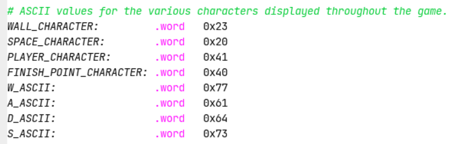
At the start of the game, the player is prompted to select a level with the choices being 1, 2 and 3. Depending on the level chosen, the player will get a different amount of time to reach the finish point (see table below). After the player has selected a level, the game begins and the timer starts to tick down. The player agent starts off from a predefined position (start position). Only parts of the walls that are inside the player's view are displayed on the screen. Nothing that is outside the maze except the finish point is shown on the screen. The player agent can be moved left, right, up and down by pressing the a, d, w, and s (lower cases) keys respectively. The player agent can only move to a position that is not occupied by a wall. Just below the maze along the left edge of the screen is a timer that counts down the number of seconds that are specfied by the game level. The player's objective is to reach the finish point before this timer reaches zero.
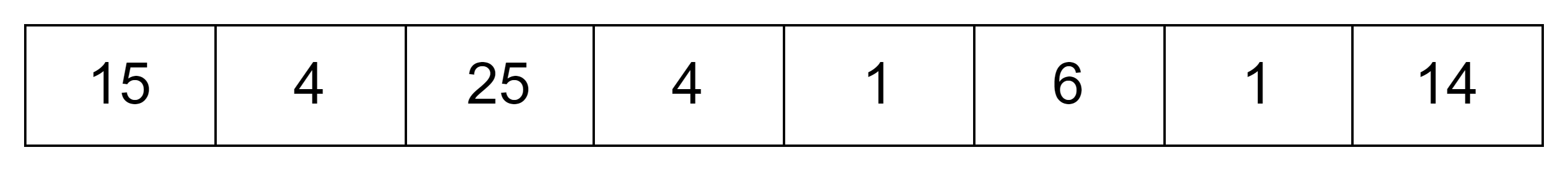
The initial time that the player gets depending on the level chosen is given below:
| Game Level | Initial Time |
|---|---|
| 1 | 60 |
| 2 | 30 |
| 3 | 20 |
In order to implement this game, your program must be able to read user input, print output and manage a timer. The input is not read from the console and the output is not printed to the RARS console. Instead input must be read by handling the interrupts caused by the keyboard and the output must be printed to the "Keyboard and Display MMIO Simulator" that gives RISC-V programs the ability to print character through memory-mapped IO. The game includes 2 screens namely the level select screen and the gameplay screen. These are described below.
When testing, provide the path to input text file (eg. test_maze.txt) at program arguments in the RARS
simulator.
The maze built with test_maze.txt looks like this. Note that this is just to show you what the maze
looks like. It ignores the players view box so the whole board can be seen. Your final program should NOT print the
whole board like this.
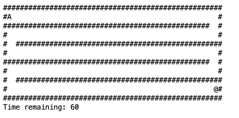
Here the player is represented by the character A while the finish point is represented by the
character @.
The finish point is shown on the screen even though it is outside the player's view. You can also see that nothing
happens
when the player tries to move to a position that is occupied by a wall. After the player has moved to the finish
point, the
game ends (the timer stops ticking and pressing keys does nothing).
The maze is a grid with the location of each cell described by its x-y co-ordinate. The top-left of the maze has coordinates (0,0). The grid size is determined by the x and y cordinates of the cell on the lowest-right corner of the grid.
For example a grid with lowest-right coordinate (125, 25) is a 126x26 grid because the indices in the grid start from 0.
Each wall is a contiguous array of cells that prevent the movement of the player. Walls must be horizontal (running left to right) or vertical (running top to bottom). Each wall is described by its starting and ending cells.
The size of the grid, the start position of the player, the finish point, the walls and draw distance are
predefined.
They are stored in a text file (eg. test_maze.txt). The name of
the file is passed to the program as a command line argument.
You can use this file as a reference to create new mazes for testing.
common.s file defines two global variables PLAYER_X_POS and
PLAYER_Y_POS that will hold
the initial co-ordinates of the player when your game's entry point (function maze) is called.
FINISH_POINT_X and
FINISH_POINT_Y respectively.
x and y coordinates of the maze are passed as arguments
to the maze
function. The max x and y are inclusive. The game is guaranteed to fit inside the max values, and the only thing
that should be drawn outside of the maze size is the timer.x coordinate, start y coordinate, end
x coordinate and end y
coordinate. Each integer is represented by 1 word in memory, so a full wall structure contains 4 words.
They are all inclusive. The walls are guaranteed to be horizontal or vertical. You will
be given an array of "wall structs" where each struct is laid out as:

x
<= End x
y
<= End y
Suppose that the player is
currently at the cell
(x, y). Further, suppose that the view distance of the player in the x and
y
direction is vd_x and vd_y
respectively. Then the upper leftmost cell that of the player views is
(x - vd_x//2, y - vd_y//2), where the //
operator represent integer division eg 9//2 = 4. Similarly, the lower right-most cell that the
player views has coordinates
(x + vd_x//2, y + vd_y//2).
Watch the video below for a concrete example of this process.
Let W.start_x represent the x co-ordinate of the start point of any given wall
W. We
define W.end_x, W.start_y and W.end_y
similarly. Then any given cell with co-ordinates (x, y) is part of a wall if and only if there exists a
wall
W such that both of the
following conditions hold:
W.start_x <= x <= W.end_xW.start_y <= y <= W.end_yIn order to implement this game you need to check if a given cell is part of a wall quite frequently. For example, every time the player moves, the game needs to check if the cell the player is trying to move to is part of a wall or not. Further every time the player moves the game needs to redraw the player's view which is essentially going through all the cells in the view and printing out a "#" character in the positions that are walls. Doing the check described above every time you need to check a cell is very inefficient because essentially you have to go through the entire array of walls for each cell in the worst case. This problem can be dealt with by having an in-memory representation of the entire maze in the form of a 2D array. Before the start of the game, the game can construct a 2D array such that positions that are walls in the maze are set to 1 while the positions that are not walls are set to 0 in the corresponding positions in the array. As an example, suppose that the cell in the maze at co-ordinates (9, 24) is a wall, then the 2D array must have a 1 in the [24][9].
There is a more efficient way of dealing with view redrawing where you only redraw parts that change but we are not considering such a way in order to make the code simpler.
This lab uses external interrupts from hardware. The role of four CSRs (Control and Status Registers) are important for the use of interrupts:
ustatus (User Status Register, CSR#0) is a 32-bit
register that controls and manages user-level interrupts in the hardware thread
(hart). To enable user-level interrupts set the 0th bit of this register
to 1.uie (User-Interrupt Enable Register, CSR#4) is a 32-bit
register that controls the types of interrupts that are enabled using a bitmask.
Bits 4 and 8 are relevant for this lab. The 4th enables user-level timer interrupts.
The 8th bit enables user-level external interrupts. These bits must be set to 1 to
enable interrupts from the timer and the keyboard.utvec (User Trap-Vector Base-Address Register, CSR#5)
is a 32-bit register that controls where interrupts are handled. The register
holds the address of the interrupt handler that should be called when an interrupt
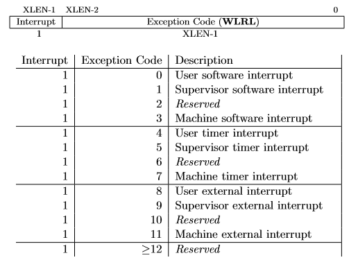
or exception occurs.ucause (User Trap Cause Register, CSR#66) is a 32-bit
register that identifiies which type of interrupt is being handled. After an exception or
an interrupt, this register holds the interrupt/exception code to help identify
its cause. An exception code is stored in the first 31 bits of ucause and the
last bit indicates whether or not it was an interrupt or an exception. To
check what type of exception/interrupt occurred refer to the table. uscratch (Temporary resgister to be used freely in the user trap handler, CSR#64)
is described below.These CSRs can be set by using the CSR instructions. For example, to enable
user-level interrupts in ustatus use "CSR Read/Write Immediate"
instruction: csrrwi zero, 0, 0x1. Or use pseudo-instructions to read
and write to the CSR registers. For example:
    csrr    t0, 4   # read from CSR#4 to t0

    csrw    t0, 6   # write whats in t0 to CSR#6

    csrwi   0, 0x4 # write 0x4 to CSR#0
Once an interrupt is raised it must be handled in the interrupt
handler created in this assignment. An interrupt handler is
analogous to a normal function but there are some key
differences. An interrupt can occur at any time, therefore the
handler must guarantee that all registers are restored to their
original values after the handler finishes. Thus, the handler must
save any register that it uses (not just the s
registers) and the handler must restore the original values to
these registers before returning. Also, the instruction
uret must be used to leave the interrupt handler
instead of the jr ra or ret instructions that are used to
return from a normal function. Again, a student should not call functions exterior to the handler if they are
using the user stack pointer. More of this is discussed below in
Saving Registers in the Interrupt Handler.
Use the Keyboard and Display MMIO Simulator, available under the
"Tools" menu in RARS, to interact with the simulator . Display the
simulator in the display section, and input commands in the keyboard
section. Don't forget to click "Connect To Program" after assembling the program
and before running it.
Generally, devices have two registers associated with them, a control, and a data register. The control register relays information about the device's state, and the data register relays data to or from a device. A description of the control and data registers for the keyboard and display can be found in the Memory-Mapped IO section.
A separate keyboard interrupt occurs for every key pressed when the keyboard interrupts are enabled. Therefore, the user program receives one character at a time.
In RISC-V, timing functionality is managed by the timing hardware thread
, maintaining the time asynchronously and allowing the program to raise
an interrupt at a specific time. To do this the core keeps track of the time in
the 64-bit register time which holds the current time (in milliseconds)
since the program started. To generate a timer interrupt at a specified time,
the value in the register timecmp must be set. Each time the timecmp
register is used, the student must reset the timecmp register with the new time
each time . A description of the
time and timecmp registers can be found in the
Memory-Mapped IO section. To simulate RISC-V timing functionality
use the Timer Tool under the "Tools" menu in RARS. Don't forget
to click "Connect To Program" and "Play" after assembling the program and before
running it each time you run the program.
Memory-mapped IO allows interaction with external devices through an interface pretending to be system memory. This mapping allows the processor to communicate with these devices using the load-word and store-word instructions. Here are the memory mappings and descriptions of important I/O registers for this lab:
| Register | Memory Address | Description |
|---|---|---|
| Keyboard control | 0xFFFF0000 |
For keyboard interrupts to be enabled, bit 1 of this register must be set to 1; after the keyboard interrupt occurs, this bit is automatically reset to 0. |
| Keyboard data | 0xFFFF0004 |
The ASCII value of the last key pressed is stored here. |
| Display control | 0xFFFF0008 |
Bit 0 of this register indicates whether the processor can write to the display. While this bit is 0 the processor cannot write to the display. Thus, the program must wait until this bit is 1. |
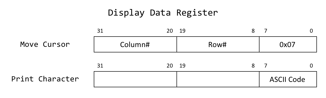
| Display data | 0xFFFF000C |
When a character is placed into this register, given that the display control
ready bit (bit 0) is 1, that character is drawn onto the display. If the
character is the bell character (ASCII code 0x07) the display will
move the cursor and the bits 8-19 and 20-31 correspond to the row and column
respectively. View the image. |
| Time | 0xFFFF0018 |
This is a read-only register that holds the time since the program has started in milliseconds. |
| Timecmp | 0xFFFF0020 |
When the value in this register is less than or equal to the value in
time a timer interrupt occurs. Writing to this register is
required to set up a timer.
|
Reading or printing syscalls cannot be used in this program. Instead, the program must use the interrupt/poll system to interact with the keyboard and the display.
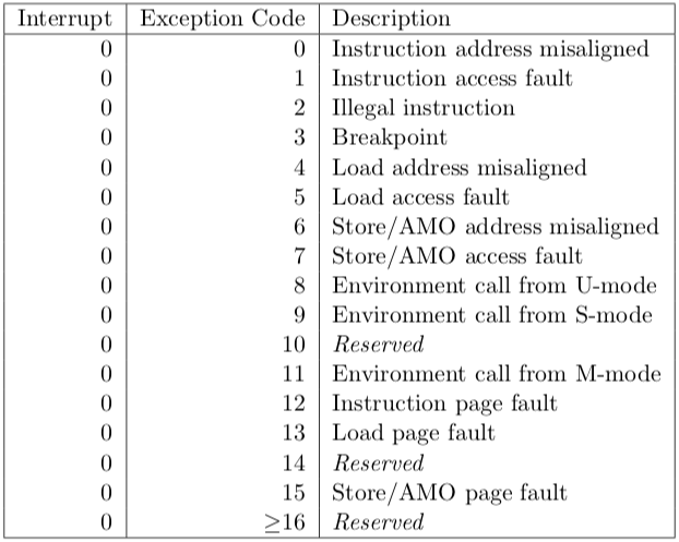
When executing RARS with your own handler, runtime errors won't be shown in RARS as usual. Thus, a section of the handler that prints the line where an error occurred and the error code is provided. Use the table to the right to identify the error.
Make sure the handler does not call any functions. This is because the handler is not a function and hence it
must
restore every register that it uses, even the t and a registers. On the other hand
functions are
not required to preserve t and a registers.
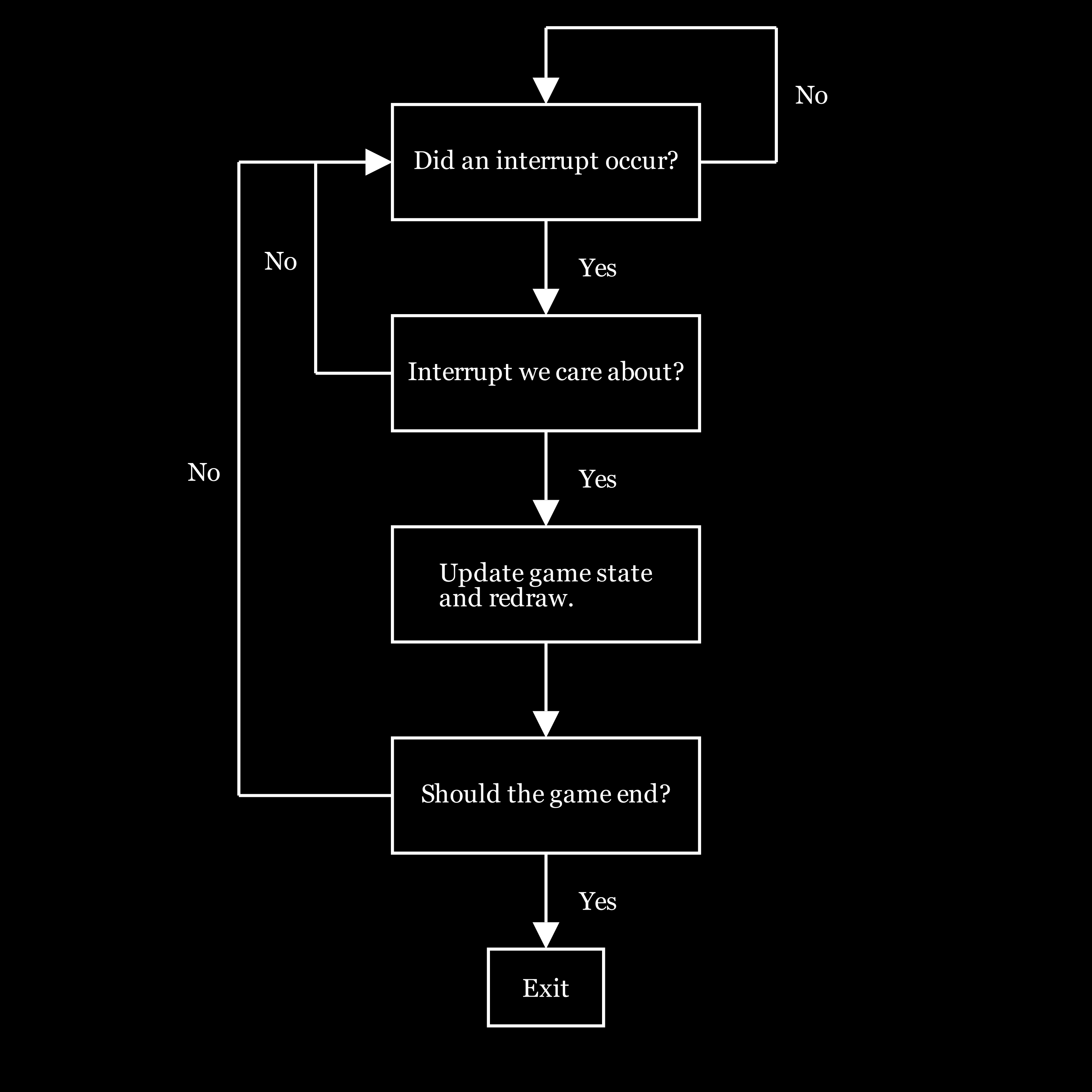
There are two phases in the execution of the game: reading the level of the game; and playing the game. Each of these phases can execute in a loop that redraws the display when there is an interruption caused either by the input of a command or by the timer. A possible design would be to reprint the display for every iteration of the loop. However, such a design could produce a flickering in the screen in certain types of monitors. Therefore a better design is to only update the screen when there is an update in the game state. The interrupts we care about in this game are the keyboard interrupts when "1", "2" or "3" are pressed during the level selection stage and the keyboard interrupts caused by "w", "a", "s" or "d" keys along with timer interrupts during the gameplay stage
This mechanism can be implemented by using a global variable to act as a flag to let the game loop know when an interrupt has occured. The handler can be programmed to set this flag when an interrupt occurs along with setting another global variable to allow the game to identify the cause of the interrupt. The game loop waits for the interrupt flag to be set by the handler. Once an interrupt occurs the game loop reads the cause of the interrupt and changes the game state accordingly. Note that after an the game has successfully responded to an interrupt, it must reset the interrupt flag to its default state.
The following lines appear in the .data section of
common.s:
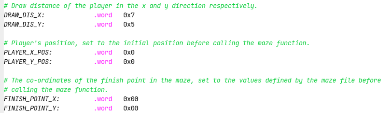
The usage of these variable is discussed in the technical details section. Note that you must use the view distances specified by these variables in your program. This helps us grade your solution.
You may add any other global variables in your maze.s file that could be used to
help run your program.
In addition to these variables, common.s also has some other global variables defined for your
convenience.
These include:
When an interrupt is raised, the program is paused and execution is transferred to
the interrupt handler. utvec holds the address of the interrupt handler that should be called when an interrupt or exception occurs.To ensure that the program can safely resume execution after
returning from the handler, the registers used by the handler must be saved upon
entering the interrupt handler and restored before returning. The registers cannot be
saved using the stack pointer because the stack pointer may be corrupted. Therefore, in
common.s we have allocated memory labeled iTrapData where
your handler may save registers. In common.s we have also placed the
address of iTrapData into the control status register #64,
uscratch. You can use uscratch and the CSR instruction
csrrw to save and restore all the values of registers used in the
handler.
After returning from the handler, all registers must have the same value as when the
program paused and uscratch should contain the address of the
iTrapData. The first instruction executed in the handler and the last
instruction executed before returning from the handler should be
csrrw a0, 0x040, a0, where a0 is chosen by convention.
Here is some sample code that saves two registers and a0 in the
interrupt trap data:
      handler:

      # swap a0 and uscratch
      csrrw   a0, 0x040, a0     # a0 <- Addr[iTrapData], uscratch <- PROGRAMa0

      # save all used registers except a0
      sw      t0, 0(a0)         # save PROGRAMt0
      sw      s0, 4(a0)         # save PROGRAMs0

      # save a0
      csrr    t0, 0x040         # t0 <- PROGRAMa0
      sw      t0, 8(a0)         # save PROGRAMa0

      ...
Non-re-entrant handler: It is up to you how you manage the memory allocated for iTrapData.
If you allocate a specific address to save a given register --- for example, register s0 is always
saved in Addr[iTrapData]+4 --- then your handler is not re-entrant.
You cannot enable interruptions while you are handling an interruption because doing so could cause the first
value of s0 that you had saved to be overwritten.
Re-entrant handler: An elegant solution to create a re-entrant handler is to implement a stack in the
memory area reserved for iTrapData.
The solution would have to handle an interrupt stack pointer. It would have to ensure that space is
allocated in this stack for a new interruption frame
before interruptions are re-enabled. Once space is reserved in the interrupt stack to save the registers that the
handler will use, then interrupts can safely be re-enabled. In this case we have a re-entrant handler.
It would be difficult to create a set of tests to determine if a handler is re-entrant. Therefore, in this lab we do not require the implementation of a re-entrant handler. It is acceptable to keep interruptions disabled while an interruption is being processed.
Write assembly code for the following functions in the file named maze.s
maze:
a0: Pointer to the array that holds the information regarding the walls in the format
specified here.a1: Number of "wall structs" in the array.a2: Pointer to an array that can be used to store the maze in-memory as a 2D array.
Guaranteed to be large enough to hold the maze.a3: The max x co-ordinate of the maze.a4: The max y co-ordinate of the maze. handler:
handlerTerminate
is provided. It should catch interrupts/exceptions unhandled by the student handler, terminating the
program and
providing debugging messages
jal ra, handler. Instead the address of the handler should be stored in the
utvec control status
register (CSR #5) at the start of the program. When an interrupt
is raised, the execution of the program jumps to the instruction address stored in utvec
buildMaze
a0: Pointer to the array that has wall info the format as specified in the spec. a1: The number of "wall structs" in the array.a2: Pointer to the array to store the maze.a3: Max x co-ordinate of the maze.a4: Max y co-ordinate of the maze.checkIsWall
a0: The x co-ordinate of the point to check.a1: The y co-ordinate of the point to check.a2: Pointer to the 2D array representing the maze.a3: The max x co-ordinate of the maze, this is needed for calculating the row offset.a0: 1 if the point is a wall else 0. intToStr
a0: The integer that is to be converted to a string.a0: The ascii characters corresponding to the integer in the lower 2 bytes.a0 is 13, then the output a0
will be 0x00003331.
printChar (the codes for this function have been given to you)
a0: The character to print.a1: The row to print the given character.a2: The col to print the given character.printStr (the codes for this function have been given to you)
a0: The address of the null-terminated string to be printed.a1: The row to print the given string.a2: The col to print the start of the given string.waitForDisplayReady (the codes for this function have been given to you)
Write additional functions as needed. The result of unit testing will be displayed in the standard output.
The program only provides unit testing for a small portion of the functions due to the nature of the program.
It's very important that you do your own testings to ensure the game can run and behave properly.
Code from the materials provided in this course can be used in the solution as
long as the source is acknowledged. For example,
displayDemo.s in Code/Demo/ may be helpful
for printing to the Keyboard and Display MMIO Simulator
display.
Assignments too short to be adequately judged for code quality will be given a zero.
buildMaze(4%)checkIsWall(4%), intToStr(2%).There is a single file to be submitted for this lab:
maze.s should contain the code for both the interrupt handler
and the function maze.
main label to this file.include "common.s"Code folder of the git repository