
CMPUT 229 — Computer Organization and Architecture I
Lab 5: Control-Flow Graph
Creator: Ayokunle Amodu, Assisted by: Ishaan Bagai
Introduction
This is the first of two labs focused on the fundamentals of flow analysis used in compiler design. The solution for this lab constructs and analyzes a Control-Flow Graph (CFG). A CFG is a fundamental data structure used in compilers to represent the possible execution paths of a program, establish dominance relationships (If curious, see the Wikipedia page), and help the compiler perform optimizations such as the Dead Code Elimination (DCE) implemented in Lab 6.
Your Task
Your task is to correctly populate the provided data structures and output the complete control-flow graph (CFG) information for the given RISC-V assembly function. This includes:
- Identifying basic blocks
- Computing edges
- Determining successors and predecessors
- Ensuring all data structures are properly formatted and terminated with their respective sentinel values
- Printing the number of basic blocks
-
For each basic block:
- Printing the basic block ID
- Printing the instructions
- Printing the successors
- Printing the predecessors
Background
What is a Control-Flow Graph?
A Control-Flow Graph (CFG) is a directed graph that visually represents the flow of control within a program. To understand a CFG, let's first break it down into its key components:
- Basic Blocks
- Edges
- Predecessors and Successors
A basic block is a unit of control-flow that represents a sequential block of code where instructions execute strictly from start to finish. A segment of code is considered a basic block if it follows these rules:
- Once execution enters a basic block, all instructions within that block must be executed.
- Branches or jumps can only occur as the final instruction of a basic block.
- Only the first instruction of a basic block can be the target for a branch or jump.
The edges in a Control-Flow Graph denote the possible flow of control between basic blocks. A conditional branch is the origin of two edges: one to the target of the branch and one fall-through edge. An unconditional jump is the origin of a single edge to its target. Fall-through edges exist between consecutive basic blocks when control may fall through from one to the other. A control-flow edge signifies a possible path that the program's execution may take.
Description:
- Predecessor: A block Bi is a predecessor of a block Bj if there is an execution path from Bi to Bj.
- Immediate Predecessor: A block Bi is an immediate predecessor of a block Bj if there is an edge from Bi to Bj.
- Successor: A block Bj is a successor of a block Bi if there is an execution path from Bi to Bj.
- Immediate Successor: A block Bj is an immediate successor of a block Bi if there is an edge from Bi to Bj.
Notes:
- A block can have any number of immediate predecessors (multiple paths may converge).
- A block can have at most two immediate successors (fall-through or branch) because a conditional branch can only have two successors: the target and the fall-through.
Now that the components of a Control-Flow Graph (CFG) have been defined, let's walk through an example of a CFG highlighting these components.
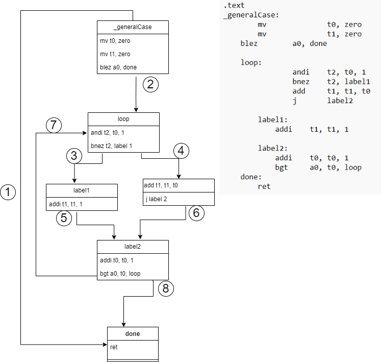
_generalCase function is divided into basic blocks.
Notice the flow of control, the instructions in each block, and the
edges between the blocks.
Here is a high-level analysis of the above image:
- The specifics of deciding what the basic blocks are discussed in the section below, but do note the execution begins at the first instruction/label of the function and this is the entry block.
- Edges labelled 1, 2, 3, 4, 5, 6, 8 are forward edges i.e. they point to a block that is later in the execution order. Edge 7 is a back edge i.e. it points to a block that is earlier in the execution order.
-
Consider the block with the label
loopand its corresponding instructions:- If the branch is false, the control flow follows edge 4 and execution goes to the fall-through successor block
- If the branch is true, the control flow follows edge 3 and execution goes to the target successor block
-
Apart from the two successor blocks, the
loopblock also has a predecessor, the_generalCaseentry block
An intra-procedural CFG represents the control flow within a function. An inter-procedural CFG also captures control flow across function calls and return statements. Inter-procedural CFGs are more complex because they must match each function call edge with its corresponding return edge. This lab focuses solely on intra-procedural CFGs. In flow analysis used in compilers, the inter-procedural flow is represented using a call graph which is not explored in these labs.
Implementation Notes
Basic Block Leaders
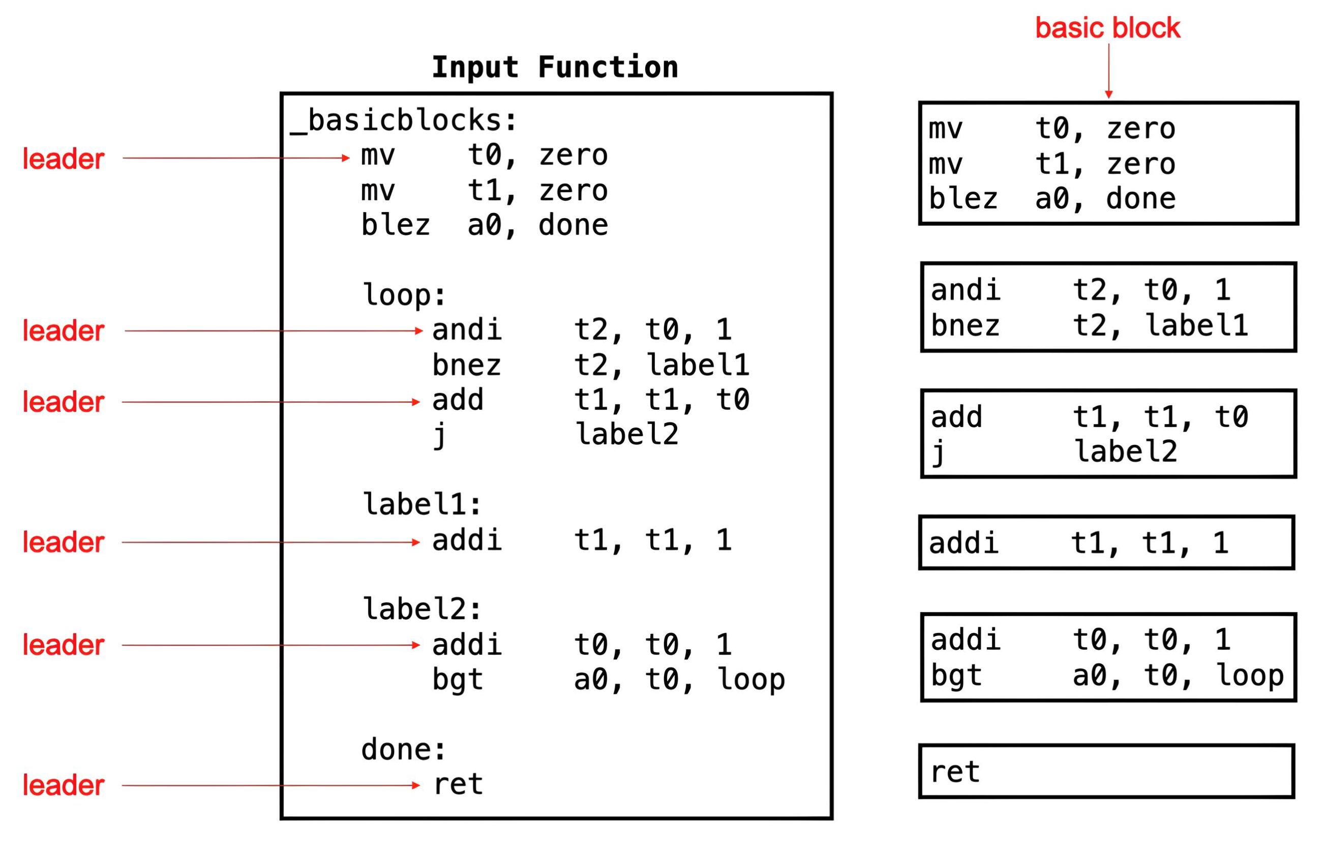
To construct a Control-Flow Graph (CFG), the first step is to divide a function into its constituent basic blocks. The first instruction of each basic block is a block leader. The following rules identify block leaders:
- The first statement in a function is a leader.
- Any statement that is the target of a branch or jump is a leader.
- Any statement that immediately follows a branch or jump is a leader.
Once the leaders are identified, the following rule determines the instructions in a basic block:
- A basic block is formed by a leader and the subsequent instructions up to, but not including, the next leader.
According to these rules, the _basicblocks function has
six leaders, resulting in six basic blocks as illustrated below:
Basic Block Identifiers
Often, the basic blocks in a CFG are labeled sequentially as
B0, B1, B2, and so on, starting
from the function's entry point (as seen in the CFG of the
_sample_function earlier). In this lab, each block is
uniquely identified by its leader offset (in words) from the
function's base address.
The diagram below illustrates the assembled program in memory with
resolved labels and hexadecimal instruction representations of the
_basicblocks function. The function begins at address
0x00010000, where the leader of the first block is also
located, making its identifier 0. The second block starts at
0x1001000c, which is three words from the function's
start, therefore its identifier is 3.
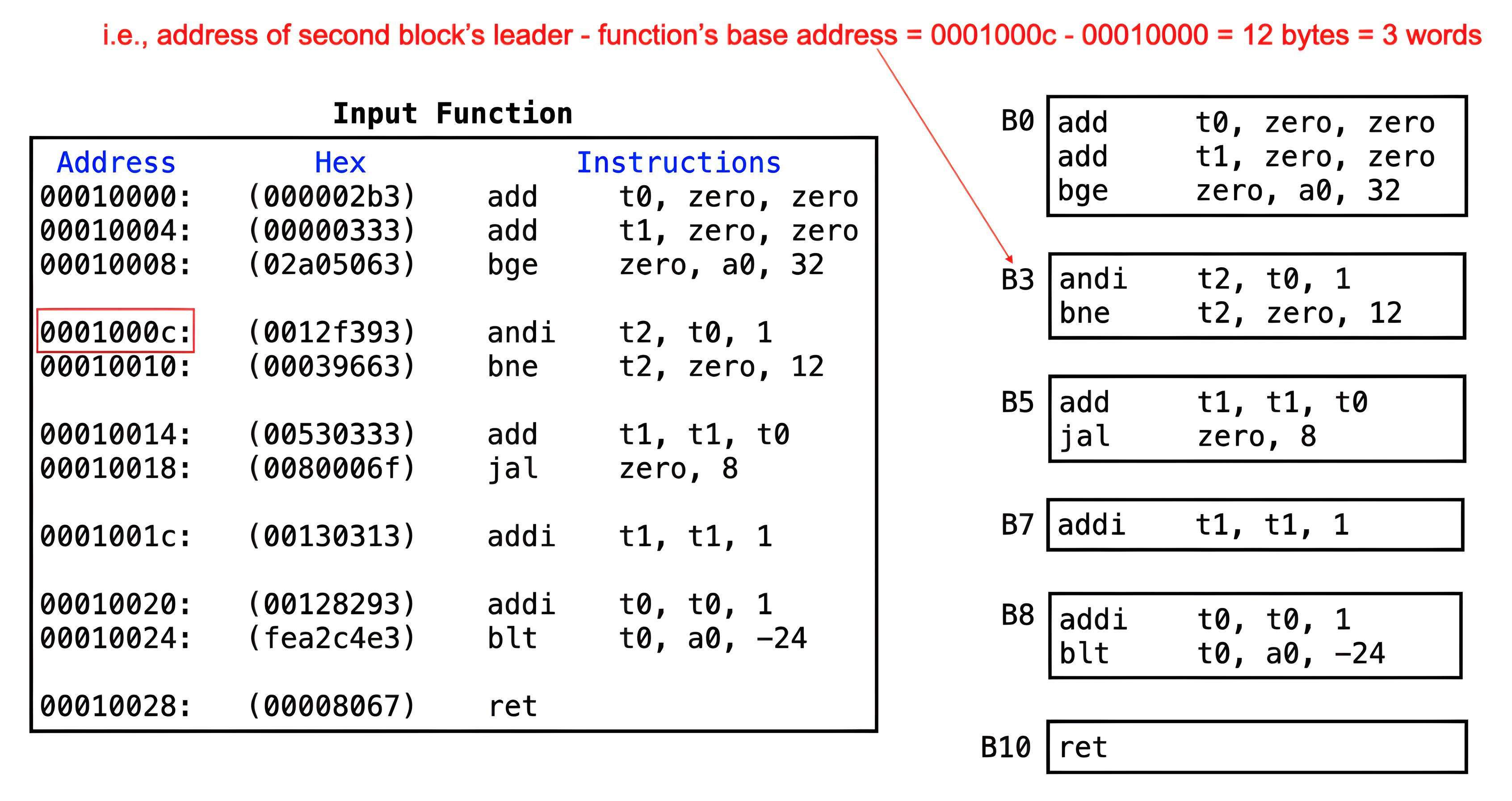
_basicblocks function above, with identifiers assigned
to each block.
The labels in an assembly program are symbols representing instruction addresses. They are used to indicate the target offsets for branches and jumps, but do not appear in the final executable.
Pseudo-Instructions
RISC-V assembly includes pseudo-instructions, which are higher-level
operations that simplify coding but are translated into one or more
actual instructions within its instruction set architechture (ISA)
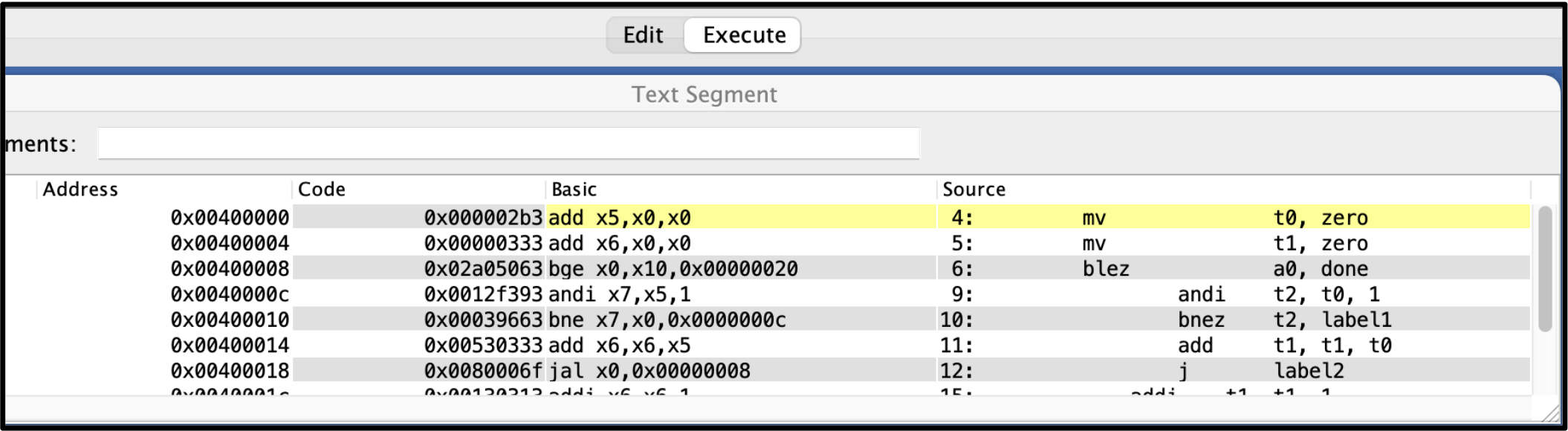
during assembly. To illustrate this, let's examine how the
_basicblocks function is assembled in RARS below.
Consider the mv (move) instruction. This
pseudo-instruction is translated into an add instruction.
For example, mv t0, zero becomes
add t0, zero, zero. Both achieve the same result of
setting the t0 register to 0, but the pseudo-instruction
offers a more intuitive syntax for the programmer.
Decoding Instructions
The RISC-V ISA uses a fixed 32-bit instruction format. Decoding is a
two-level process: a 7-bit opcode identifies the
instruction format, and within each format, a 3-bit
funct3 field specifies the specific instruction.
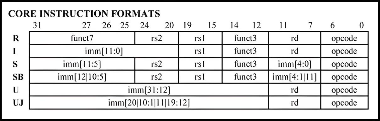
opcode and has a 3-bit funct3 field,
funct3 and opcode are always in the same
position
Let's disassemble the fourth instruction (0x0012f393) of
the _basicblocks function as an example:
0x0012f393 = 0000 0000 0001|00101|111|00111|0010011
                                  ^^^       ^^^^^^^
                                  funct3    opcode
opcode  = 0010011
funct3  = 111
The opcode indicated that this is an
I-type instruction, and the funct3 field
specifies that it is an andi instruction (Refer to the
RISC-V Green Sheet for the table mapping opcodes to instructions).
Data Structure Descriptions
Some data structures are provided in this lab. Memory for these
structures has already been pre-allocated in common.s,
and pointers to them are passed to the function
getControlFlowGraph, in your solution file. A solution to
this lab will populate these structures.
Description: An array of
words containing the input function's
instructions. Ends with a sentinel value of -1
(0xFFFFFFFF).
In this lab, input functions are represented as an array of RISC-V
instructions. Every RISC-V instruction can be represented as a
word in memory (e.g., addi t1, t1, 1 =
0x00130313). Thus, a function can be represented as
an array of words.

instructionsArray for the
_basicblocks function, showing the instruction
layout as it appears in memory.
Description:
An array of bytes where each index
corresponds to an instruction in the
instructionsArray at the same index. If the
instruction is a leader, its corresponding byte will be 1; 0
otherwise. Ends with a sentinel value of -1
(0x000000FF).

leadersArray for
the _basicblocks function, which stores the offsets
of all identified block leaders.
Description:
An array of bytes representing the
unique identifiers of each basic block in the function's CFG. Each
identifier corresponds to the offset (in words) of the block's
leader from the function's base address. Elements appear in
execution order. Ends with a sentinel value of -1
(0x000000FF).

blocksArray for
the _basicblocks function, which stores structured
metadata for each basic block in the CFG.
Description:
An array of bytes representing the last instruction in each basic block within the CFG. Each element corresponds directly to the difference between the function's base address and the last instruction of each basic block, each stored in sequential order. Ends with a sentinel value of -1 (0x000000FF).

blockEndsArray for the
_basicblocks function, which records the index of
the last instruction belonging to each basic block.
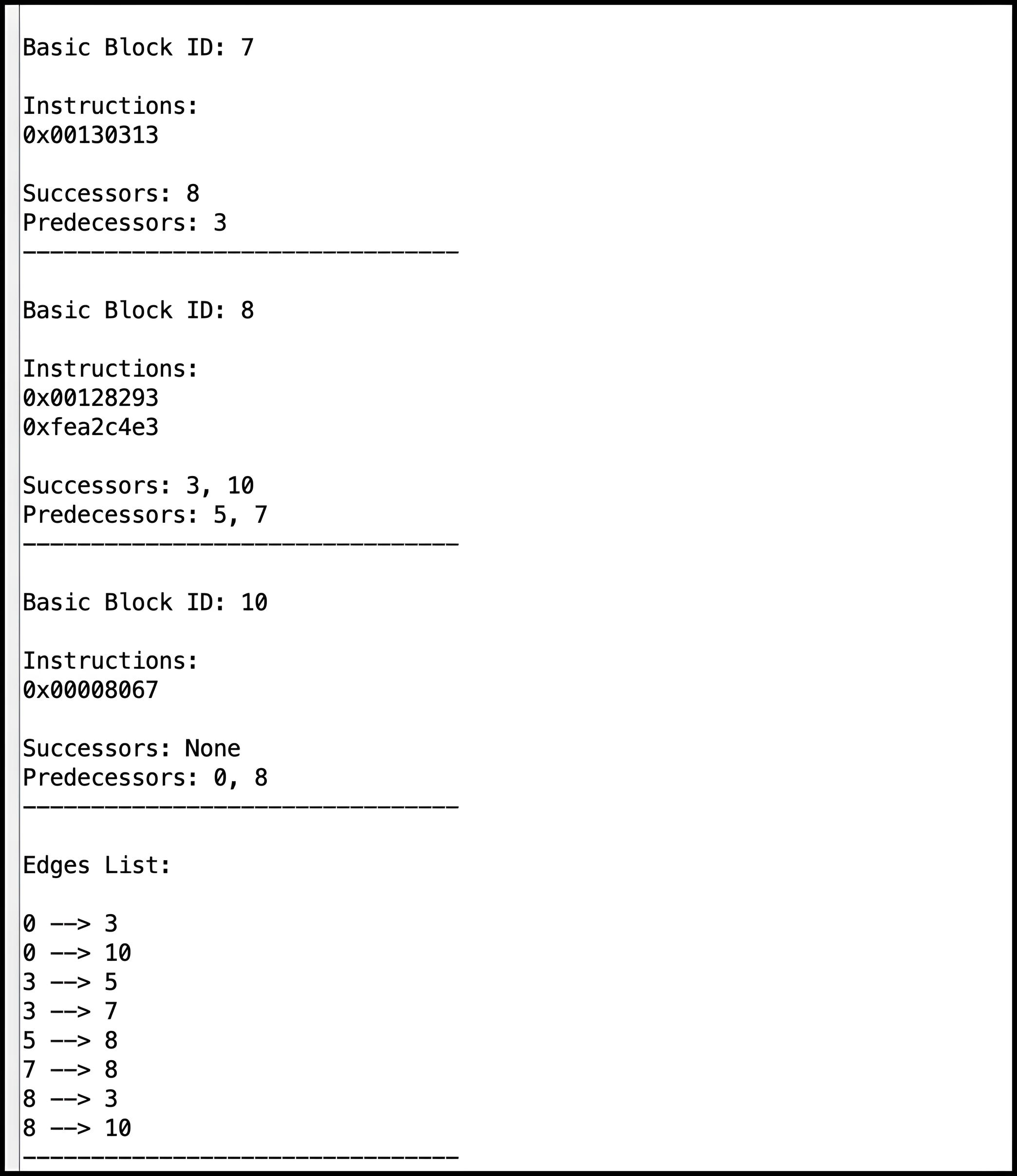
Description: An array of pairs of bytes representing the edges in the input function's CFG. Each pair encodes a source and target block index. Ends with a sentinel pair of bytes (-1, -1).
The structure of the edgesList must satisfy the following ordering rules:
- Edges must appear in ascending order of their source blocks.
- For edges with the same source, targets must also be ordered.
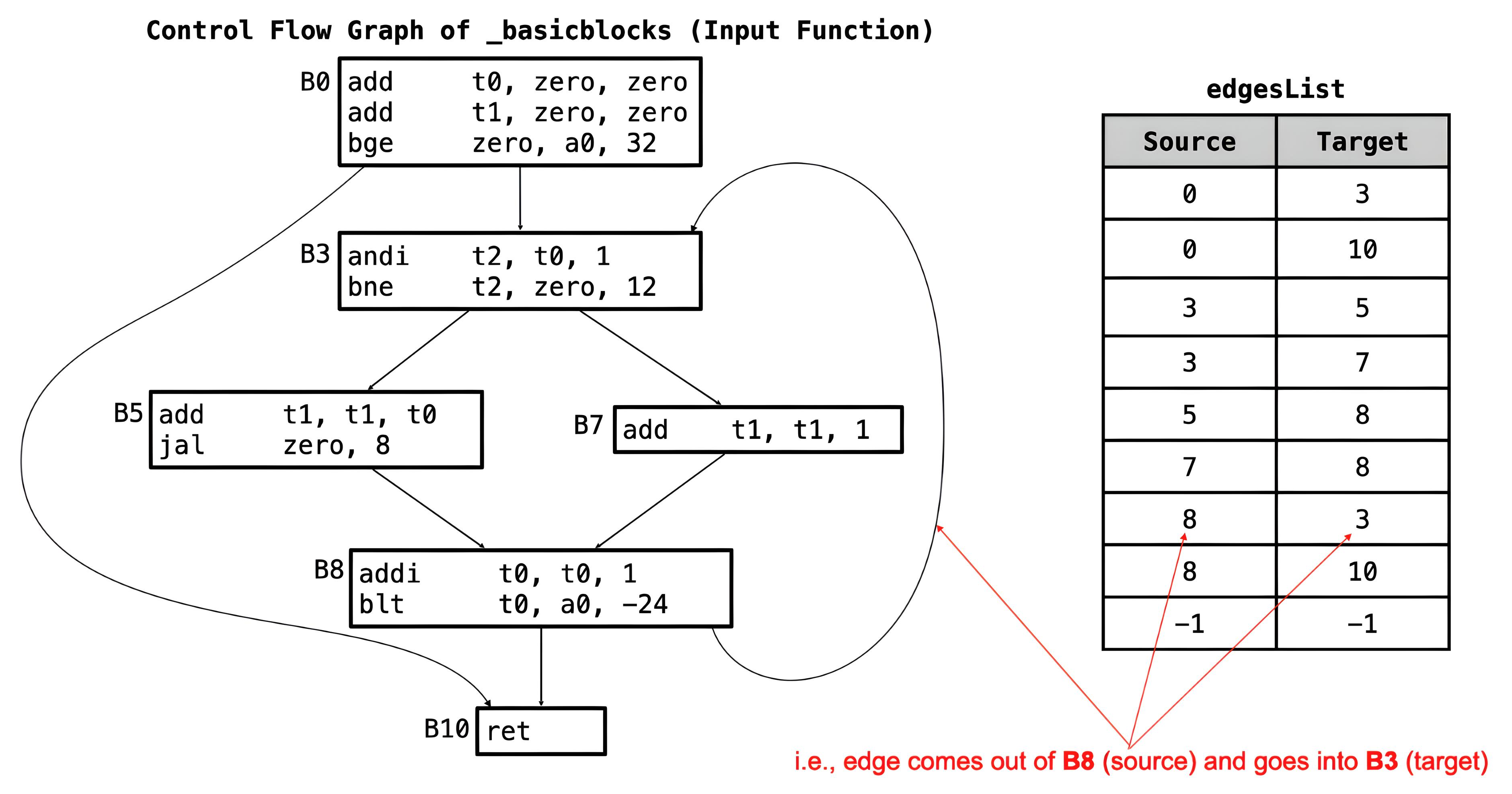
edgesList for the
_basicblocks function above is
[(0,3) , (0,10) , (3,5) , (3,7) , (5,8) , (7,8) , (8,3) ,
(8,10) , (-1,-1)].
Description:
Successors are stored in two arrays of
bytes represented as two structures:
firstSuccessorsArray and
secondSuccessorsArray.
These arrays hold the immediate successors of each basic block in the function's CFG. Each element of the successors arrays corresponds to a basic block, stored in sequentially.
Each element of each of the successor arrays corresponds to a basic block.
-
Two successors:
- The earlier one goes in firstSuccessorsArray.
- The later one goes in secondSuccessorsArray.
-
One successor:
- Stored in firstSuccessorsArray.
- -1 in secondSuccessorsArray.
-
No successors:
- -1 in both arrays.
Both arrays end with sentinel byte -2 (0xFE).
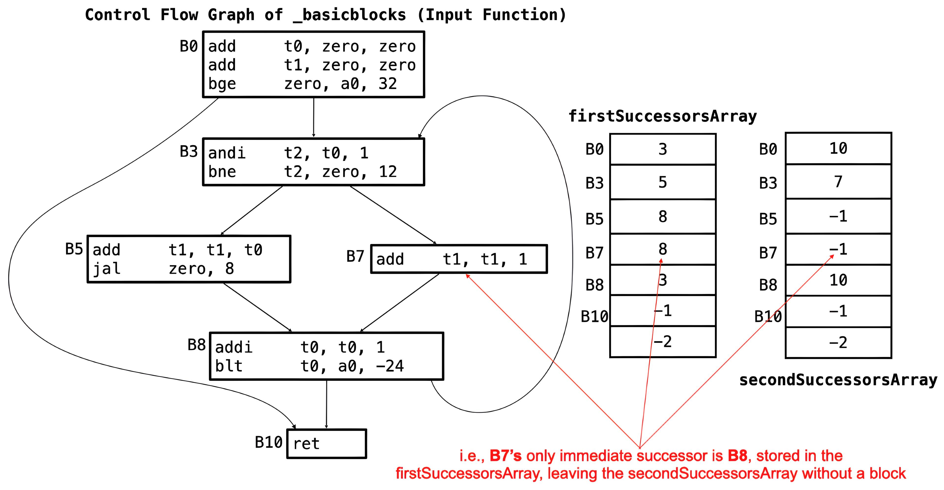
firstSuccessorsArray and
secondSuccessorsArray for the
_basicblocks function.
Description: Predecessors are stored using two data structures:
-
predecessorsArrayis an array of words containing pointers to each block'spredecessorsList. -
predecessorsListis an array of bytes, dynamically allocated at runtime containing the immediate predecessors of each basic block (for implementation details, refer to the Dynamic Memory Allocation section).
Each index of predecessorsArray corresponds to a
basic block in order. (for example, B0 corresponds to index 0 of
predecessorsArray, B3 corresponds to index 1 of
predecessorsArray, etc. in our
_basicblocks
function)
There are two cases:
-
If a block has predecessors:
-
The corresponding element in
predecessorsArraypoints to thepredecessorsListof the block. -
Its predecessors are stored in the list pointed to by the
address in
predecessorsArray, at that index, in ascending order. -
The list ends with a sentinel value of -1
(
0xFF).
-
The corresponding element in
-
If a block has no predecessors:
-
The corresponding element in
predecessorsArrayis set to -1 (0xFFFFFFFF).
-
The corresponding element in
The predecessorsArray ends with a sentinel value of
-2 (0xFFFFFFFE).
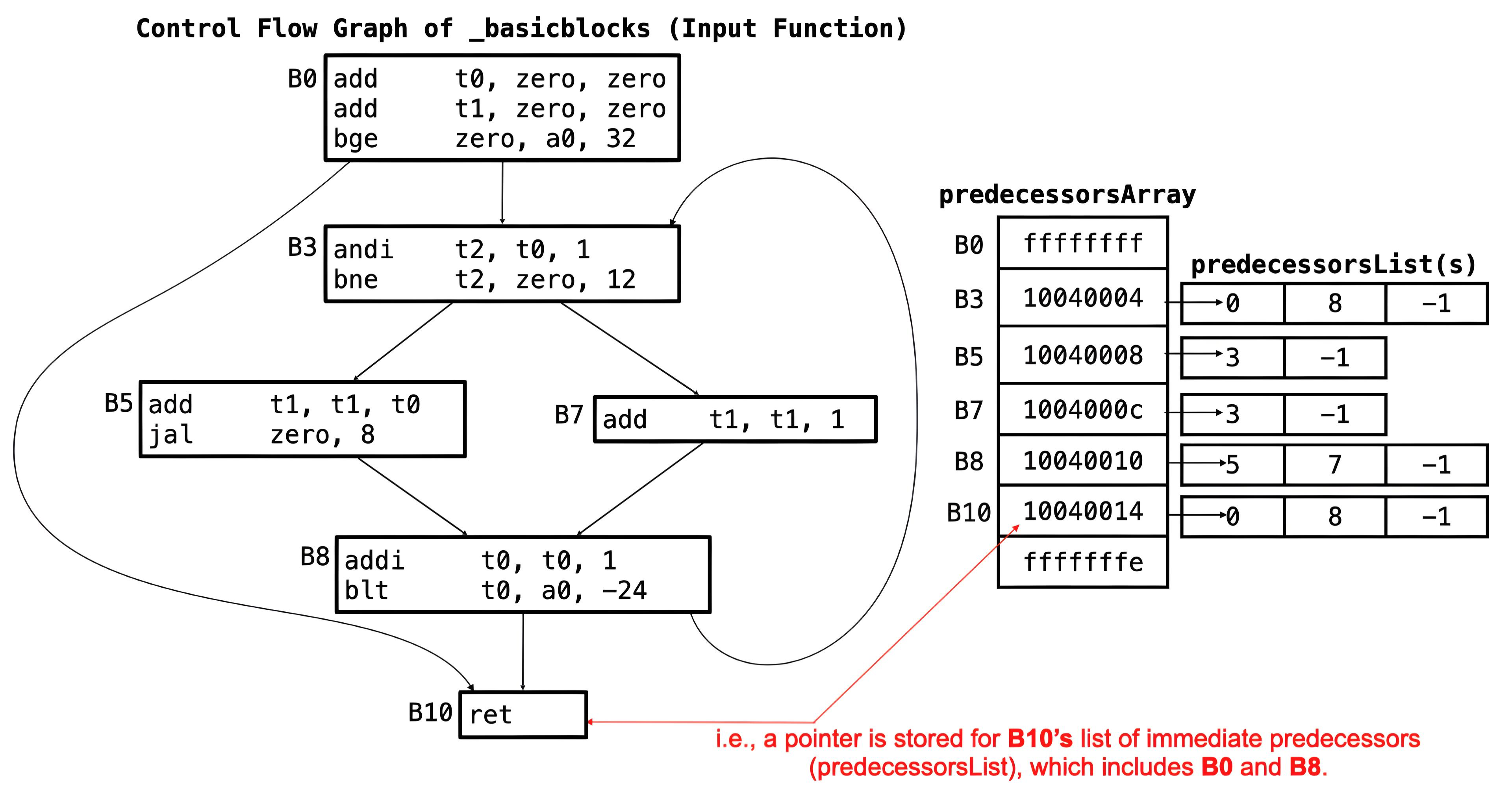
predecessorsArray for the
_basicblocks function, which stores pointers to
each block's predecessors. Note that the addresses in the
predecessorsArray are mock addresses based on the
_basicblocks function ( see above in
blockEndsArray Section)
Dynamic Memory Allocation
A block can have any number of immediate predecessors, making it impractical to allocate a fixed number of arrays as done with successors. In such cases, where the maximum size of a data structure are unknown, dynamic memory allocation is an excellent solution. To use dynamic memory allocation:
- Determine the required space at runtime
- Allocate that memory on the heap; and
-
Store the data in the allocated space. Use the
sbrkecall (code 9) in RARS to allocate heap memory (see RARS Environment Calls page).
Assignment Specification
The directive .include "common.s" in the provided
solution file (controlFlowGraph.s) causes RARS to execute
the code in the file common.s before the solution file.
The code in common.s reads a binary file provided in the
program arguments, initializes the arguments, calls
getControlFlowGraph, parses the custom data structures
populated by the solution, and prints the CFG information extracted
from the parsed data.
Function Signatures
Write all the following RISC-V functions in the file
controlFlowGraph.s:
Description:
This is the entry point of the program. It constructs the control-flow graph
(CFG) for a RISC-V assembly function by identifying basic blocks and
computing edges, block boundaries, successors and predecessors.

Arguments:
    a0: a pointer to the instructionsArray
    a1: a pointer to the leadersArray
    a2: a pointer to the blocksArray
    a3: a pointer to the blockEndsArray
    a4: a pointer to the edgesList
    a5: a pointer to the firstSuccessorsArray
    a6: a pointer to the secondSuccessorsArray
    a7: a pointer to the predecessorsArray

Returns:
NoneDescription:
Iterates through the instructionsArray and identifies the basic blocks and
their respective leaders to fill the leadersArray as described earlier
(for more implementation details refer to the leadersArray section).
Arguments:
a0: a pointer to the instructionsArray
a1: a pointer to the leadersArray
Returns:
NoneDescription:
Responsible for filling in the blocksArray with the unique identifiers of each
basic block and for filling in the blockEndsArray with the last instruction of
each basic block. Refer to the data structure descriptions earlier for the
format of these arrays.
Arguments:
a0: a pointer to the leadersArray
a1: a pointer to the blocksArray
a2: a pointer to the blockEndsArray
Returns:
NoneDescription:
Stores the source-target pair of each edge in the edgesList for the function's
control-flow graph, in ascending order of source-target pair. Both source and
target are identified by their block identifier as stored in the blocksArray.
For implementation details, refer to the edgesList section.
Arguments:
a0: a pointer to the instructionsArray
a1: a pointer to the blocksArray
a2: a pointer to the blockEndsArray
a3: a pointer to the edgesList
Returns:
NoneDescription:
Stores the immediate successors of each basic block in ascending order in the
firstSuccessorsArray and secondSuccessorsArray. There can be at most two
successors. Refer to the successorsArrays section for implementation details.
Arguments:
a0: a pointer to the blocksArray
a1: a pointer to the edgesList
a2: a pointer to the firstSuccessorsArray
a3: a pointer to the secondSuccessorsArray
Returns:
NoneDescription:
Responsible for computing the correct predecessor information for a block by
using 2 data structures.
(1) predecessorsArray: An array of pointers, each pointing to a predecessorsList.
(2) predecessorsList: A dynamically allocated flat array of bytes listing the predecessor block IDs.
Refer to the predecessorsArray description above for more information.
Arguments:
a0: a pointer to the blocksArray
a1: a pointer to the edgesList
a2: a pointer to the predecessorsArray
Returns:
NoneHelper Functions
In RISC-V assembly, every function must have a return statement. The
following are examples of valid return statements: ret,
jr ra, and jalr zero, 0(ra). The
controlFlowGraph.s file already includes the function
labels above and each ends with a return statement. Do not change the
names of these functions, as they are called for unit testing in the
common.s file.
There are two helper functions located at the bottom of the solution file. They include:
-
getBranchImm: Extracts the sign-extended immediate from a branch instruction (SB-type), such asbeq,bne,bge,bltu,bgeu, etc. -
getJalImm(optional implementation): Extracts the sign-extended immediate from a jump instruction (UJ-type), such asjal. This function is not implemented by default, and no unit test is provided, so you will need to implement and test it yourself to ensure it works correctly.
Assumptions and Notes
-
The input function provided to
controlFlowGraph.swill consist of at most 254 instructions. - There will be no calls to other functions within the input function.
-
All unconditional jumps within the input function will be
jal, notjalr(which is used for returns). Therefore, do not handlejalras a control-flow instruction; instead, treat it as a normal statement.
Testing your Lab
This lab has a single program argument: the binary file of the input
function (e.g.,
nested_loop.bin). You must provide the full path of this
file in the program arguments section in the Execute tab
on RARS. Ensure that the path adheres to the following criteria:
- No quotation marks around the path.
- No spaces in the path or file names.
Consider the path
Users/JohnDoe/CMPUT-229/Lab 5/Code/Tests/nested_loop.bin.
The space in the folder name Lab 5 can cause issues when
trying to locate the file. It is recommended to rename it to
Lab-5 or another name without spaces to avoid any
problems.

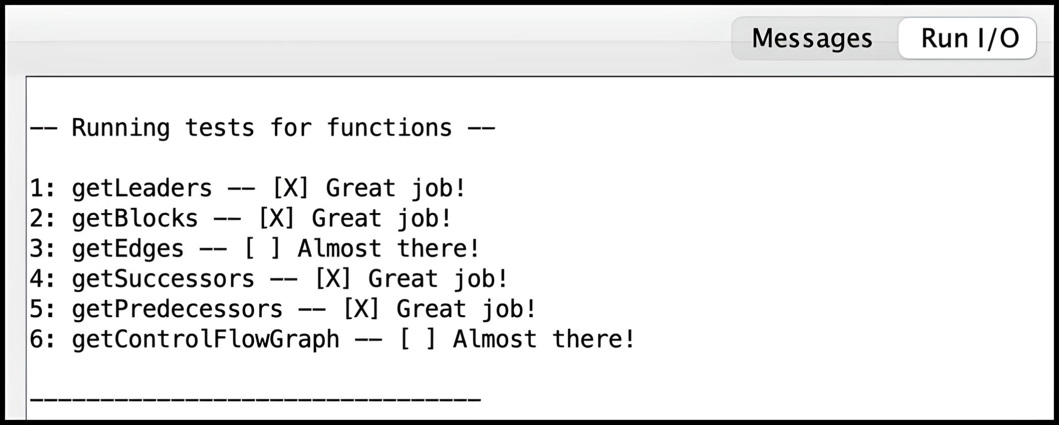
The common.s file contains some unit tests to help test
the solution. This testing works on a predefined input function and
checks whether the output from functions in
controlFlowGraph.s matches the expected output. The tests
are hardcoded and do not run on the file specified in the program
arguments. The results of the unit tests can be viewed in the
Run I/O panel of RARS.
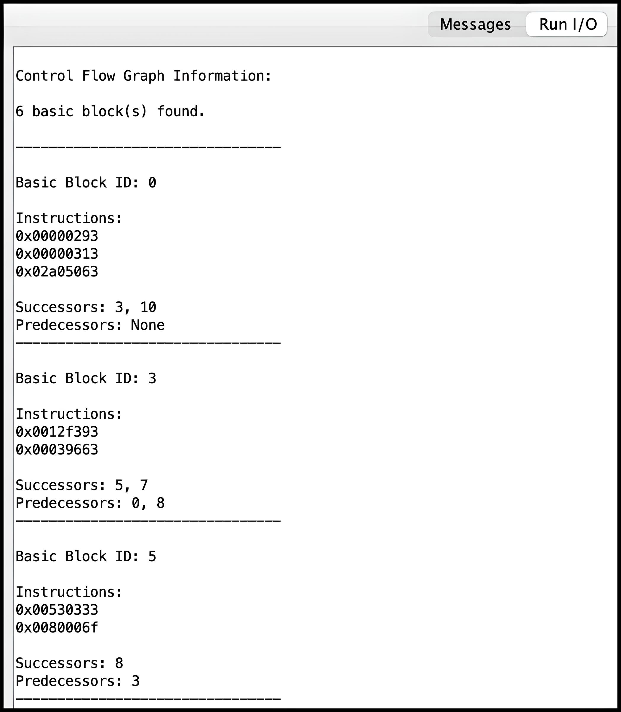
The common.s file also aids in parsing the data
structures popualted by your solution, and the CFG information can be
viewed in the Run I/O panel of RARS, following the unit
test results. Note that parsing the data structures relies on all of
them ending with their respective sentinel values. This ensures that
the parsing function can correctly identify the end of each
structure's data. It also relies on the
predecessorsArray having valid pointers (if any). There
are a few input functions with their corresponding expected outputs
(parsed CFG information) provided in the Tests folder,
which is included in the Code folder. Although passing
the tests is essential, it does not guarantee full marks as they are
NOT EXTENSIVE. You can create your own corner-case
tests to ensure that your code is correct.
Creating Test Cases
To create a test case, write a RISC-V function (e.g,
INPUT_FUNCTION.s) in an assembly file. Then, type in the
following command in the terminal:
rars a dump .text Binary <INPUT_FUNCTION.bin> <INPUT_FUNCTION.s>
The binary file generated by this command can serve as a program
argument in RARS for the solution file
controlFlowGraph.s. Use the full file path, ensuring to
specify the binary (.bin) file for input, not the assembly (.s) file.
Instruction Disassembly
One way to debug a solution to this lab, is to create the CFG of an
input function and compare with the solution's output. The
common.s file parses the data structures populated by the
solution allowing you to inspect each block and view the instructions
that it contains. Instructions are represented in hexadecimal format,
so a disassembler can be helpful for verifying that the instructions
are correctly placed within their respective blocks.
This lab has an additional folder in the Code folder
called Disassembly. It contains files that perform
instruction disassembly which is the process of translating
hexadecimal instructions to their corresponding RISC-V instructions.
This code is from an
Open Source RISC-V Disassembler. Please contact a TA if you run into any issues using the code.
To utilize this disassembler, follow these steps:
-
First, compile the file
print-instructions.cusing a C compiler. For example, from the terminal, execute the command:gcc print-instructions.c -o disassemblerorclang print-instructions.c -o disassembler. - Create a file containing the hexadecimal instructions to disassemble by copying and pasting your RARS output into a text file.
-
Run the executable with the hexadecimal text file as a program
argument. For example:
./disassembler RARS-instructions.txt.
See the README.md in the Disassembly folder
for more information.
CheckMyLab
This lab is supported in CheckMyLab. To get started, navigate to the Control Flow Graph lab in CheckMyLab found in the dashboard. From there, students can upload test cases in the My test cases table.
A test case consists of a binary file representing a single RISC-V assembly function (see Testing your Lab). It is your responsibility to ensure that the test cases you upload to CheckMyLab satisfy the assumptions stated in the Assumptions and Notes section, as some of the assumptions are non-trivial to verify automatically.
Resources
Marking Guide
Assignments too short to be adequately judged for code quality will be given a zero for that portion of the evaluation.
- 5% for
getControlFlowGraph - 15% for
getLeaders - 10% for
getBlocks - 25% for
getEdges - 10% for
getSuccessors - 15% for
getPredecessors - 20% for code cleanliness, readability, and comments
Submission
There is a single file to be submitted for this lab (controlFlowGraph.s
) and it should contain the code for your solution.
-
Do not add a
mainlabel to this file. - Do not modify the function names.
- Do not remove the CMPUT 229 Student Submission License at the top of the file containing your solution and remember include your name in the appropriate section of this text.
-
Do not modify the line
.include "common.s". -
Do not modify the
common.sfile. -
Keep the files in the
Codefolder of the git repository. - Push your repository to GitHub before the deadline. Just committing will not upload your code. Check online to ensure your solution is submitted.