
CMPUT 229 — Computer Organization and Architecture I
Lab 6: Dead Code Elimination
Creator: Ayokunle Amodu, Assisted by: Ishaan Bagai
Introduction
This is the second of two labs focused on the fundamentals of flow analysis used in compiler design. The solution for this lab implements Dead Code Elimination (DCE) on a RISC-V assembly function. DCE is a foundational optimization technique that removes code which is either unreachable or redundant, and builds directly on the Control-Flow Graph (CFG) constructed in Lab 5.
Background
What is Dead Code?
Code is considered Dead Code if it satisfies either of the following conditions:
- There is no possible path of execution that reaches it (it is unreachable)
- It is executed, but its result is never used and it has no effect on the program's observable behavior (it is redundant)
Dead code can appear not only at the instruction level but also at the block level. For example, in a control flow graph, a block that has no incoming edges from any other block is unreachable and thus can be removed without affecting the program's behavior.

Let us examine two instances of redudant dead code in our figure:
-
The instruction
li t2, 20is dead code because the result (t2) is only used for other dead instructions likeaddi t3, t2, 5. -
Within the loop, the instruction
slli t6, t4, 1is also dead code as the value computed int6is never referenced later.
How to perform DCE?
To successfully perform dead code elimination, we must first understand the concept of Liveness Analysis. A variable is said to be live at a specific point in the program if the value it holds at that point may be used in the future i.e. it is not yet overwritten or discarded.
Thus to perform DCE, we need to first perform liveness analysis. This is a two step process:
- Block-Level Liveness Analysis
- Instruction-Level Liveness Analysis
Block-Level Liveness Analysis
Block-level liveness analysis uses a fixed-point algorithm to figure out which variables are still needed at the end of each basic block in a program's control flow.
The algorithm iteratively computes the sets of variables that are live at the entry and exit of each basic block in the CFG. It continues until a fixed point is reached, where further iterations do not change the sets of live variables.
Key Sets Computed for Each Block
During this analysis, the following sets are calculated for each basic block in the CFG:
- gen: Set of variables that are generated or used within a block before any of them are killed by another instruction in the same block. These are the variables that might be needed by subsequent blocks, making them candidates for propagation to successor blocks.
- kill: Set of variables that are killed or overwritten in a block. Once a variable is killed, its previous value is no longer needed, meaning it won't be considered live after the block's execution unless it's redefined.
- live in: Set of variables that are live at the entry point of a block. A variable is live-in if it is used in the block or in any of the block's successors and is not redefined before its use.
- live out: Set of variables that are live at the exit of a block. A variable is live-out if it is used in any successor blocks. The live-out set is critical for understanding what information must be carried over to subsequent blocks for correct program execution.
Fixed-Point Algorithm Overview
liveness_analysis:
    for each block in cfg.blocks:
        block.live_in = empty_set
        block.live_out = empty_set

    worklist = []
    worklist.add(exit_block)

    while worklist not empty:
        block = worklist.pop()

        new_live_out = empty_set

        if block == exit_block:
            new_live_out = function_live_out

        for each succ in block.successors:
            new_live_out = new_live_out ∪ succ.live_in

        new_live_in = block.gen ∪ (new_live_out - block.kill)

        if new_live_in != block.live_in OR new_live_out != block.live_out:
            block.live_in = new_live_in
            block.live_out = new_live_out

            for each pred in block.predecessors:
                if pred not in worklist:
                    worklist.add(pred)
The core idea of the algorithm is to iteratively refine the
live_in and
live_out
sets until they stabilize. Initially, all sets are empty. Then:
- Start by adding the exit block to the worklist.
-
For each block, calculate its new
live_outset by taking the union of thelive_insets of its successors. Thelive_outset of the exit block is thelive_outset of the function (thelive_outset of the function is passed as a program argument to your lab solution). -
Update the
live_outset. -
Using the updated
live_outset, compute the newlive_inset using the formula:live_in = gen ∪ (live_out - kill) -
If the
live_inset changed, update it and add the block's predecessors to the worklist.
This continues until no further changes occur in any live_in set, signifying
that a fixed point has been reached. This is referred to as
fixed-point convergence.
The final live_in and live_out sets
represent precise liveness information and are needed to perform DCE.
For the purposes of this Lab, the subtraction symbol '-' is used to denote Set Difference.
Instruction-Level Liveness Analysis
After reaching fixed-point convergence at the block level, we can perform a finer, instruction-level liveness analysis to catch more precise instances of dead code. Block-level analysis may miss definitions that are never used before being redefined within the same block, these are effectively dead but still appear live at the block level.
Instruction-level analysis resolves this by examining each instruction in reverse (from last to first) within a block. This reverse pass catches redefinitions that hide unused values, allowing us to more accurately identify dead code.
Key Sets at the Instruction Level
- gen: Registers used by the instruction (e.g., source register for a load word instruction).
-
kill: Registers defined by the instruction
(typically
rdregister for an instruction). -
live in: Registers that hold values that are still
needed by subsequent instructions. Computed as
gen ∪ (live_out - kill). - live out: Registers that are live after the instruction executes, meaning these values are still required later in the program.
find_dead_code:
    for each block in cfg.blocks:
        current_live_out = block.live_out

        for each instruction in block (iterate from end to start):

            if instruction is already marked as dead:
                continue to next instruction

            new_live_in = instruction.gen U (current_live_out - instruction.kill)

            if instruction.kill == empty:
                current_live_out = new_live_in
                continue to next instruction

            if zero_register in instruction.kill:
                mark instruction as dead
                continue to next instruction

            if (instruction.kill AND current_live_out) == empty:
                mark instruction as dead
                continue to next instruction

            current_live_out = new_live_in
Dead Code Detection Algorithm
The algorithm initializes current_live_out with the
block's live_out set. It then walks through each
instruction in reverse. For each instruction:
- If it's already marked dead, skip it.
- Compute
live_in = gen ∪ (live_out - kill). -
If it defines a register that isn't live out (and isn't
zero), mark it as dead. -
Update
current_live_outto reflect the new liveness state.
This process continues for every instruction, ensuring we only keep instructions that contribute to the program's final state.
This analysis doesn't handle unreachable code or branches that always behave the same way. It assumes all program paths are possible, so some dead instructions may still escape detection.
Assignment
The goal of this lab is to perform dead code elimination (DCE) for a function written in RISC-V assembly. The task involves implementing liveness analysis to eliminate redundant dead code in the function.
You will not need to eliminate unreachable code in this lab.
Register Bit Vectors
In RISC-V, registers from x0 to x31 can be
represented as bit vectors. In this representation, each bit
corresponds to a specific register, where the bit position matches the
register number. For instance, if the register x1 is part
of a particular set, the bit in the first position of the bit vector
is set to 1, while the remaining bits are set to 0. The RISC-V green
sheet contains the matching name for each of the registers from x0
to x31.
Data Structure Descriptions
Pointers to CFG Data Structures
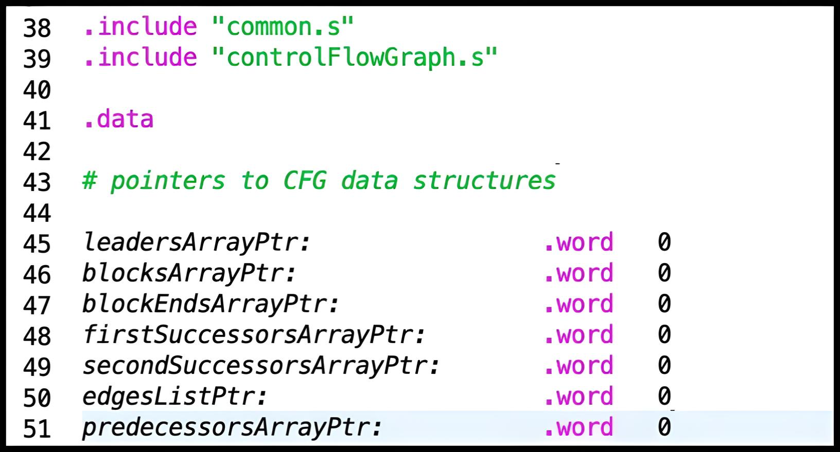
For the liveness analysis explained in previous sections, we rely on
CFG information, which you should have experience with from the
previous lab. Specifically, you'll work with the data structures
from the lab, provided here:
leadersArray,
blocksArray, blockEndsArray,
firstSuccessorsArray, secondSuccessorsArray,
and predecessorsArray.
The descriptions for these data structures can be found in
the description of Lab 5: Control Flow Graph.
edgesList is not included above as the solution
does not require filling it for completion of the lab.
Pointers to these data structures are not passed directly to the
primary function in
deadCodeElimination. Instead, they are accessed through
global pointers that are defined for you at the top of your solution
file. The common.s file initializes these pointers with
the addresses of their respective arrays.
For the successful completion of this lab, you do not require a working solution to the previous lab. You will instead be provided with a binary file that contains the data necessary to initialize the data structures mentioned above. This file will be passed as an argument to the RARS simulator when you run your solution.
DCE Data Structures
These are the data structures that need to be filled to solve the lab.
Memory for these
structures has been pre-allocated in the common.s file,
and pointers to them are passed to the
deadCodeElimination function in your solution file
deadCodeElimination.s. Your task is to populate these
structures with the necessary liveness and dead code information.
Description:
An array of words representing the intput function's instructions.
Ends with a sentinel value of -1 (0xFFFFFFFF).
In this lab, input functions are represented as an array of RISC-V
instructions. Every RISC-V instruction can be represented as a
word in memory (e.g., addi t1, t1, 1 =
0x00130313). Thus, a function can be represented as
an array of words.
Description:
An array of words representing the gen sets for each basic block
in the input function's CFG. Each word is a bit vector where each
bit corresponds to a register that is generated (used) in that
block. For example, if a register is used in the first basic
block, the corresponding bit in the first word will be set. This
array helps in determining which values are necessary for
subsequent blocks in the flow of the program. Ends with a sentinel
value of -1 (0xFFFFFFFF).
Description:
An array of words representing the kill sets for each basic block
in the input function's CFG. Each word is a bit vector where each
bit corresponds to a register that is killed (overwritten or
redefined) in that block. For example, if a register is
overwritten in the first basic block, the corresponding bit in the
first word will be set. Ends with a sentinel value of -1
(0xFFFFFFFF).
Description:
An array of words representing the live-in sets for each basic
block in the input function's CFG. Each word is a bit vector where
each bit corresponds to a register that is in the live-in of a
given block. Ends with a sentinel value of -1
(0xFFFFFFFF).
Description:
An array of words representing the live-out sets for each basic
block in the input function's CFG. Each word is a bit vector where
each bit corresponds to a register that is in the live-out of a
given block. Ends with a sentinel value of -1
(0xFFFFFFFF).
Description:
An array of bytes representing the dead code status of each
instruction in the input function. Each byte corresponds directly
to an instruction. For example, the first byte corresponds to the
first instruction, the second byte to the second instruction, and
so on. If the instruction is identified as dead code, its
corresponding byte will be 1; if it is not dead code, the byte
will be 0. Ends with a sentinel value of -1 (0xFF).
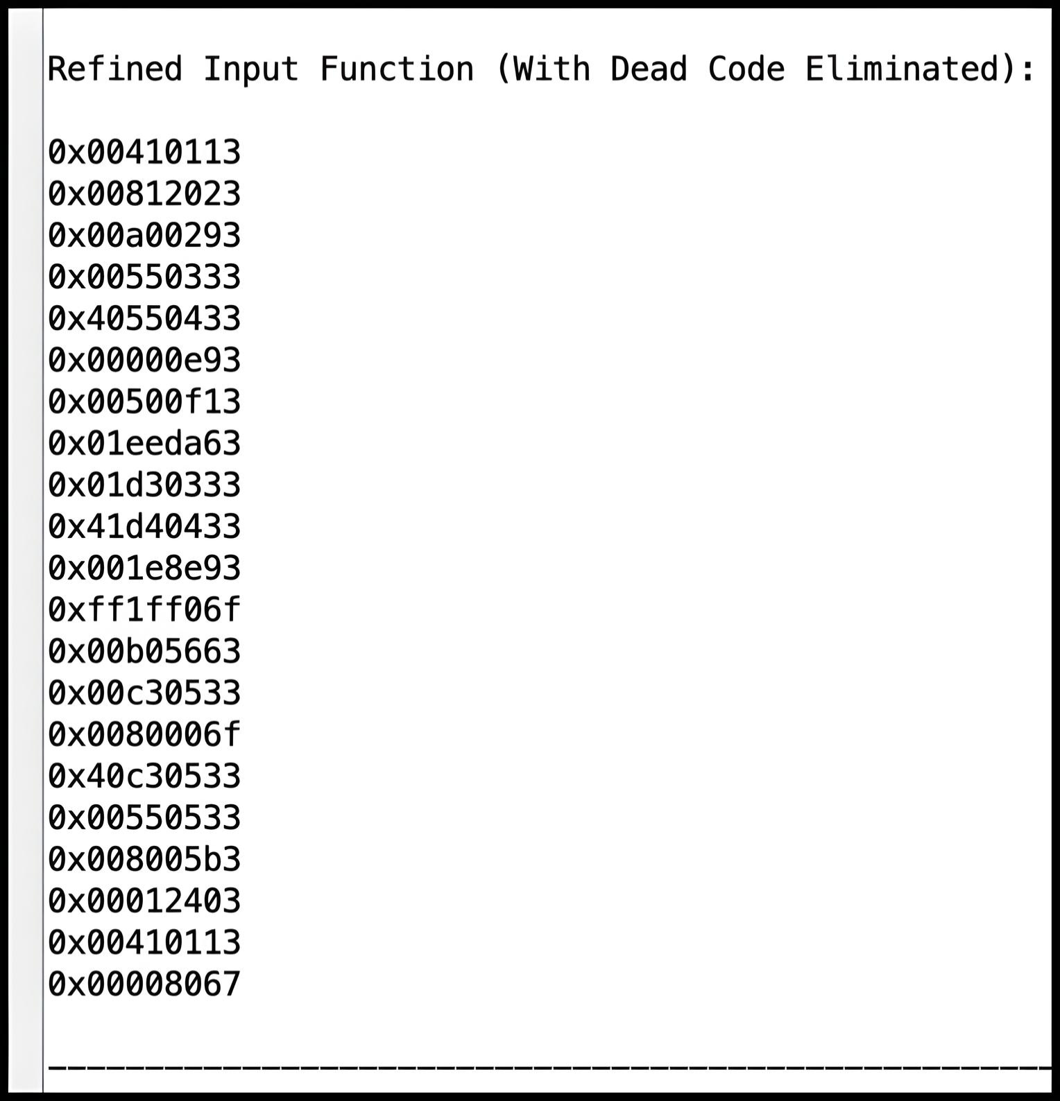
Description:
An array of words representing the refined instructions of the
input function after dead code elimination. Each word corresponds
to an instruction in the refined function. Ends with a sentinel
value of -1 (0xFFFFFFFF).
As a reminder, the blocksArray index is used to access
related data in other arrays. For more details on how
blocksArray is utilized, please refer to the previous
lab.
Worklist Data Structures
The worklist is used to manage the blocks that need to be processed. It helps ensure that each basic block in the control flow graph (CFG) is revisited until no further changes are detected in its liveness information. The specific data structures that make up the worklist and their roles in this process are provided below.
Description:
The workList is a circular queue used to manage a
list of basic blocks to be processed. It operates with a fixed size and
maintains two indices:
-
workListHeadIndex: Points to the position in the list where the next block will be removed. -
workListTailIndex: Points to the position in the list where the next block will be added.
The workList uses an array where:
-
An entry of -1 (
0xFF) indicates an empty slot. - When the list is full, adding a new block will result in an error if there is no space.
- When the list is empty, removing an block will return an error if there are no items to remove.
The workList is implemented as a circular queue,
meaning that when the tail index reaches the end of the array, it
wraps around to the beginning, and similarly for the head index.
Description:
An array of bytes corresponding to each block in the input
function's CFG. Each byte represents whether the block is
currently in the worklist. If the block is in the worklist, the
byte will be set to 1; otherwise, it will be set to 0. Ends with a
sentinel value of -1 (0xFF).
Writing a Solution
The directive .include "common.s" in the provided
solution file (deadCodeElimination.s) causes RARS to
execute the code in the file common.s before the solution
file. The code in common.s reads a binary file provided
in the program arguments, initializes the arguments, parses the
data structures populated by your solution, and prints the liveness
information extracted from the parsed data.
Function Signatures
Write all the following RISC-V functions in the file
deadCodeElimination.s:
Description:
Performs an iterative analysis to remove dead code from the input function.

Arguments:
    a0: Pointer to the instructionsArray.
    a1: Pointer to the genArray.
    a2: Pointer to the killArray.
    a3: Pointer to the liveInArray.
    a4: Pointer to the liveOutArray.
    a5: Input function's live-out set.
    a6: Pointer to the deadCodeArray.
    a7: Pointer to the refinedInstructionsArray.

Returns:
None.Description:
Computes the gen and kill sets for each block in the control flow graph.
Arguments:
a0: Pointer to the instructionsArray.
a1: Pointer to the deadCodeArray.
a2: Pointer to the genArray.
a3: Pointer to the killArray.
Returns:
None.Description:
Computes the live-in and live-out sets for each block in the
input function's control-flow graph.
Arguments:
a0: Pointer to the genArray.
a1: Pointer to the killArray.
a2: Pointer to the liveInArray.
a3: Pointer to the liveOutArray.
a4: Function's live-out set.
Returns:
None.Description:
Marks instructions as dead within each block of the input
function's control-flow graph.
Arguments:
a0: Pointer to the instructionsArray.
a1: Pointer to the liveOutArray.
a2: Pointer to the deadCodeArray.
Returns:
a0: Dead code status (1 if dead code found, 0 otherwise).Description:
Adjusts branch and jump instruction targets based on the presence of
dead code.
Arguments:
a0: Pointer to the instructionsArray.
a1: Pointer to the deadCodeArray.
Returns:
None.Description:
Removes dead code from the input function.
Arguments:
a0: Pointer to the instructionsArray.
a1: Pointer to the deadCodeArray.
a2: Pointer to the refinedInstructionsArray.
Returns:
None.Description:
Decodes a given instruction to determine its defined and used registers.
Arguments:
a0: An instruction word.
Returns:
a0: Bit vector of the defined register.
a1: Bit vector of the used registers.Notes
-
For this lab, only the following opcodes are relevant:
- I-type (load):
0000011 - I-type (arithmetic with immediate):
0010011 - U-type (load upper immediate):
0110111 - S-type (store):
0100011 - SB-type (branch):
1100011 - R-type (arithmetic):
0110011
- I-type (load):
-
jalinstruction (used for jumps) andjalrinstruction (used for returns) are not considered to define or use any registers in this lab. - For further details, refer to the RISC-V Green Sheet: RISC-V Green Sheet.
Worklist Functions
The worklist functions have already been implemented for you at the
bottom of the solution file,
deadCodeElimination.s. These functions are needed for
managing the processing of blocks during liveness analysis and dead
code elimination. Feel free to review them to understand how they
interact with the data structures discussed above.
Description:
Initializes the head and tail indices of the workList to zero.
Sets up the workList to be empty and ready for new entries.

Arguments:
    None.

Returns:
None.Description:
Adds an item to the workList. Returns an error if the list is full.
Arguments:
a0: Item to add to workList.
Returns:
a0: 0 on success, -1 (0xFF) if workList is full.Description:
Pops an item from the workList.
Arguments:
None.
Returns:
a0: Item from workList or -1 (0xFF) if workList is empty.
In RISC-V assembly, every function must have a return statement. The
following are examples of valid return statements: ret,
jr ra, and jalr zero, 0(ra). The
deadCodeElimination.s file already includes the function
labels above and each ends with a return statement. Do not change the
names of these functions, as they are called for unit testing in the
common.s file.
In this lab, there are three helper functions with signatures provided to you. These functions are optional, and do not need to be implemented for completion of this lab:
-
adjustBranchImm: Provides a new immediate value to a branch instruction, modifying the instruction word accordingly. This function is not implemented by default and needs to be completed and tested by you. -
adjustJalImm: Provides a new immediate value to a jump instruction, modifying the instruction word accordingly. -
getBlockIndex: Finds the index of a given block in the blocksArray.
Recommended Program Flow
-
Initialize the
deadCodeArraywith all instructions set as unmarked. -
Perform the iterative analysis as follows:
-
Call
getGenKillSetsto compute the generation and killing sets. -
Call
getLiveSetsto determine the live-in and live-out sets for each basic block. -
Call
markDeadCodeto identify and mark the dead code based on the live sets. -
If
markDeadCodeindicates that new dead code was found, return to step 2.
-
Call
-
Once the loop exits (when no new dead code is found), call
fixTargetsto adjust any targets affected by the dead code removal. -
Finally, call
removeDeadCodeto eliminate the marked dead code from the program.
Assumptions and Notes
-
The input function provided to
deadCodeElimination.swill consist of at most 254 instructions. - There will be no calls to other functions within the input function.
- There is only one exit block in the input function.
-
All unconditional jumps within the input function will be
jal, notjalr(which is used for returns). Therefore, do not handlejalras a control-flow instruction.jalrwill be used exclusively for returns in this lab.
Testing your Lab
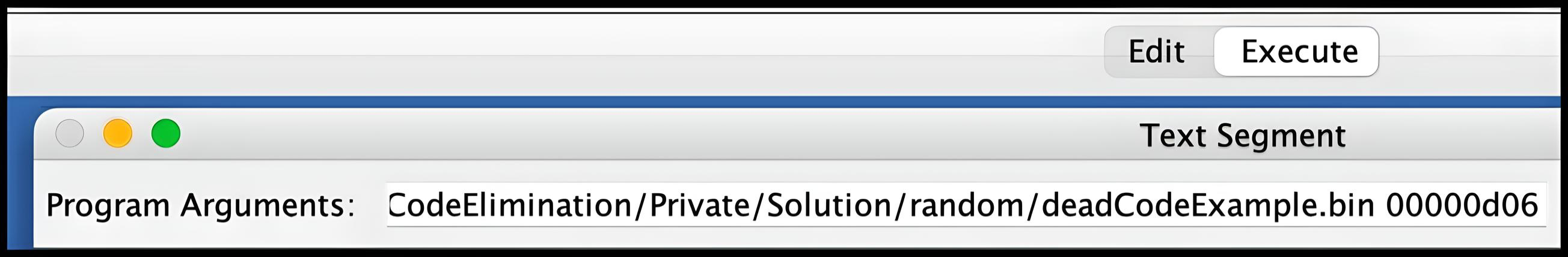
For this lab, two program arguments are required, which should be
specified in the program arguments section under the
Execute tab in RARS. They include:
-
The binary file of the input function (e.g.,
nested_loop.bin). -
The function's live-out set in hexadecimal format, provided without
the
0xprefix (e.g.,1234ABCDinstead of0x1234ABCD). The hexadecimal characters can be in either uppercase or lowercase.
When specifying these arguments, ensure that the file path to the
binary file is fully provided, with no quotation marks or spaces in
the path or file names. For example, a path like
Users/JohnDoe/CMPUT-229/Lab 6/Code/Tests/nested_loop.bin
may cause issues due to the space in the folder name
Lab 6. It is recommended to rename it to
Lab-6 or another name without spaces to avoid problems.
Additionally, ensure that the function's live-out argument is
separated by a space from the file path for proper execution.
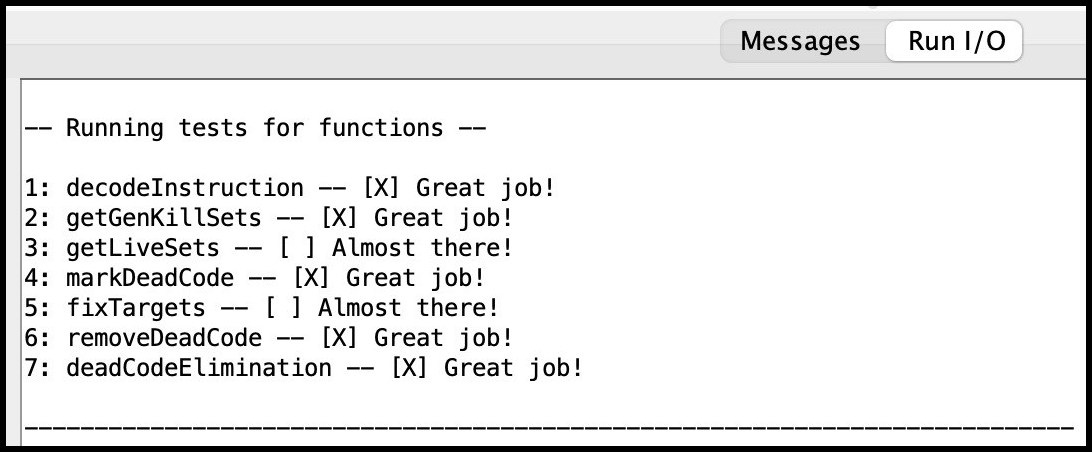
The common.s file contains some unit tests that check if
your solution correctly populates the intended arrays with the
appropriate data, which is then compared against the expected values.
These tests are hardcoded and do not run on the file specified in the
program arguments. The results of the unit tests can be viewed in the
Run I/O panel of RARS.
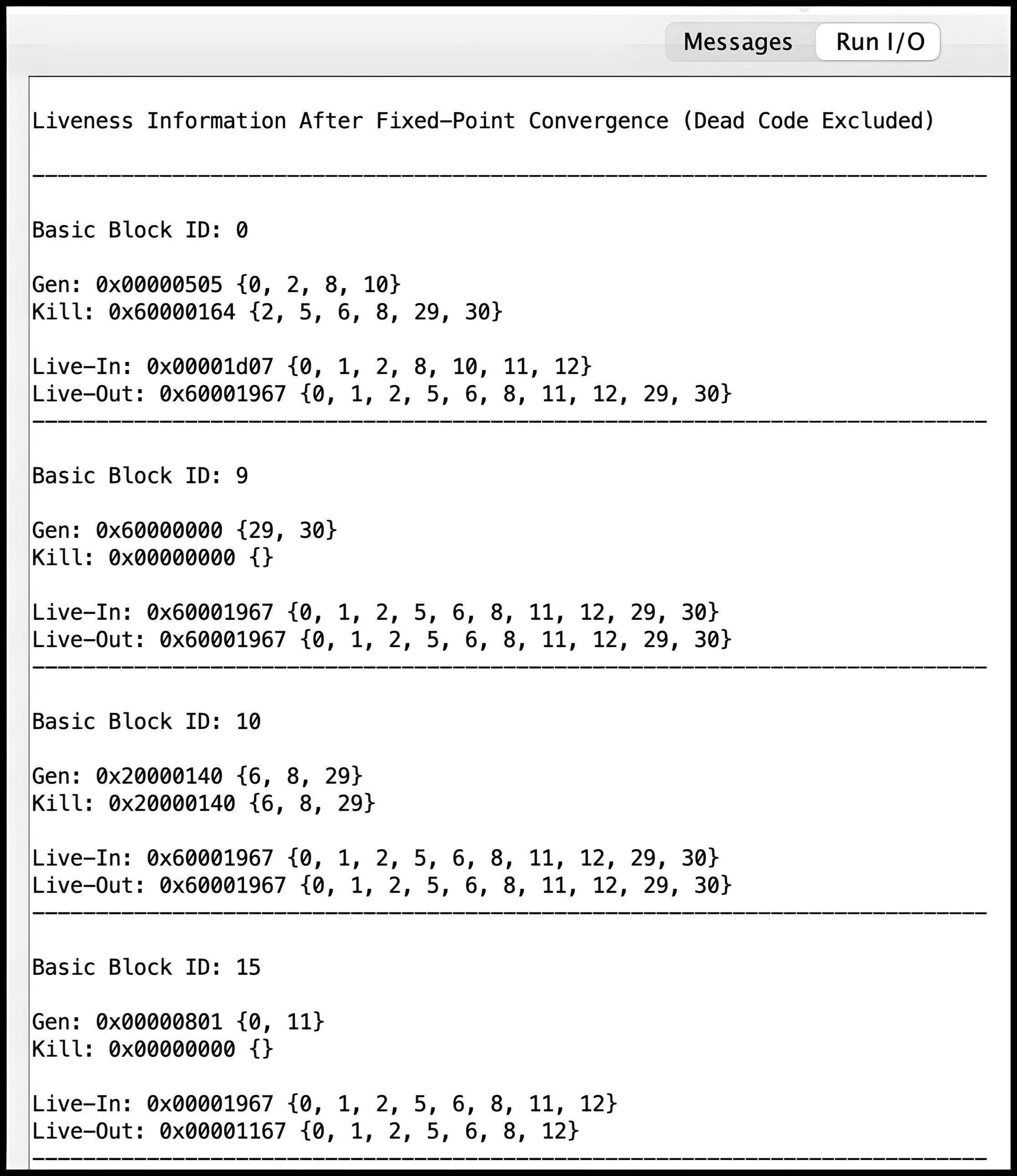
The common.s file assists in parsing the data structures
populated by your solution, displaying both the liveness information
and the refined function with dead code removed. This output can be
viewed in the Run I/O panel of RARS following the unit
test results. Several input functions along with their corresponding
expected outputs are provided in the Tests folder within
the Code directory. While passing these tests is
important, it does not guarantee full marks, so you are encouraged to
create your own corner-case tests to thoroughly validate your code.
Creating Test Cases
To create a test case, first write a RISC-V function in an assembly file (e.g.
INPUT_FUNCTION.s). Then, use the following command to generate a binary file
INPUT_FUNCTION.bin:
rars nc a dump .text Binary INPUT_FUNCTION.bin INPUT_FUNCTION.s
The binary file generated by this command serves as a program
argument to the cfg_runner tool included in your assignment repository
in the test_case_generator directory. The
cfg_runner tool is used to parse INPUT_FUNCTION.bin
and generate another binary file cfg.bin,
which can then be used as the first argument to deadCodeElimination.s.
Assuming that you have already generated INPUT_FUNCTION.bin
as described above and the current directory is the root of your assignment repository,
you can use the following command to generate cfg.bin:
test_case_generator/cfg_runner INPUT_FUNCTION.bin
Renaming cfg.bin to a more descriptive test
case name is recommended.
If you determined that the live-out of INPUT_FUNCTION.s
is 1234ABCD in hexadecimal, you would then run the test case as follows:
rars deadCodeElimination.s nc pa cfg.bin 1234ABCDInstruction Disassembly
For the provided tests, you are given the expected refined functions
with its instructions in hexadecimal format. The
common.s file processes the
refinedInstructionsArray to display the refined function
with dead code removed. While you can compare the hexadecimal
representations to identify discrepancies, using a disassembler allows
you to compare the actual instructions, offering a clearer view of any
differences.
This lab has an additional folder in the Code folder
called Disassembly. It contains files that performs
instruction disassembly which is the process of translating
hexadecimal instructions to their corresponding RISC-V instructions.
This code is from an
Open Source RISC-V Disassembler. Please contact a TA if you run into any issues using the code.
To utilize this disassembler, follow these steps:
-
First, compile the file
print-instructions.cusing a C compiler. For example, from the terminal, execute the command:gcc print-instructions.c -o disassemblerorclang print-instructions.c -o disassembler. - Create a file containing the hexadecimal instructions to disassemble by copying and pasting your RARS output into a text file.
-
Run the executable with the hexadecimal text file as a program
argument. For example:
./disassembler RARS-instructions.txt.
See the README.md in the Disassembly folder
for more information.
CheckMyLab
This lab is supported in CheckMyLab. To get started, navigate to the Dead Code Elimination lab in CheckMyLab found in the dashboard. From there, students can upload test cases in the My test cases table.
Test cases for CheckMyLab must be structured as follows:
-
The live-out of the function must be provided as a comment on the first line.
The live-out is specified as a 32-bit hexadecimal number (as described in the
Testing your Lab section).
There must be exactly one space between the
#and the live-out, and there must be no other text on the first line. - The RISC-V assembly source code for the function must begin on the second line.
An example is shown below.
# 1234ABCD
my_func:
    ...
    ret
It is your responsibility to ensure that the test cases you upload to CheckMyLab satisfy the assumptions stated in the Assumptions and Notes section, as some of the assumptions are non-trivial to verify automatically.
Resources
Marking Guide
Assignments too short to be adequately judged for code quality will be given a zero for that portion of the evaluation.
- 48% for
deadCodeElimination(correct refined instructions array output) - 6% for
getGenKillSets - 10% for
getLiveSets - 6% for
markDeadCode - 4% for
fixTargets - 3% for
removeDeadCode - 3% for
decodeInstruction - 20% for code cleanliness, readability, and comments
Submission
There is a single file to be submitted for this lab (deadCodeElimination.s
) and it should contain the code for your solution.
-
Do not add a
mainlabel to this file. - Do not modify the function names.
- Do not remove the CMPUT 229 Student Submission License at the top of the file containing your solution and remember to include your name in the appropriate section of this text.
-
Do not modify the line
.include "common.s". -
Keep the files in the
Codefolder of the git repository. - Push your repository to GitHub before the deadline. Just committing will not upload your code. Check online to ensure your solution is submitted.