
CMPUT 229 — Computer Organization and Architecture I
Lab 6: Pipelining Simulator
Author: Saumya Patel
Introduction
Overview
This lab simulates the operation of a pipelined CPU by implementing a simulator that models the flow of instructions through a classic 5-stage RISC-V pipeline.
The simulator allows a user to step through the execution of a program instruction by instruction, visualizing how each instruction moves through the pipeline stages: Instruction Fetch (IF), Instruction Decode/Register Fetch (ID), Execute/Address Calculation (EX), Memory Access (MEM), and Write Back (WB).
Each CPU cycle corresponds to an iteration of the simulation loop. The simulator prints the updated state of the pipeline at the end of each simulated CPU cycle. After all instructions have been retired and there are no instructions in the pipeline, the simulator prints the final state of the CPU registers. The output of the simulator shows how instructions flow through the pipeline and how the pipeline handles various hazards. The different types of pipeline hazards are described in the Background section.
The simulator also models cache behavior. When a memory instruction (load or store) is executed, the simulator randomly determines whether the request results in a cache hit or miss, introducing a stall when a miss occurs. This limited simulation of a memory hierarchy allows the user to see how memory-access delays propagate through the pipeline and affect the execution of subsequent instructions. See the Cache Simulator and Delays due to Cache Hits and Misses sections for more details.
The simulator tracks and displays various statistics, including:
- The total number of cycles taken to execute the program
- The cycles per instruction (CPI)
- The number of branches executed
- The number of correct branch predictions
- The number of branch mispredictions
- The number of cache hits and misses
These metrics enable an analysis of the impact of pipeline hazards, stalls, and cache behavior on simulated CPU performance.
A valid test case for the simulator is any RISC-V program that contains only supported instructions. For a list of which instructions are supported, see the Test Cases section. The test cases illustrate how different instruction sequences interact with the pipeline and cache.
Your Task
The solution for this lab consists of implementing 8 functions that will simulate the operation of a pipelined CPU (see the Functions to be Implemented).
The provided RISC-V assembly file Common.s initializes
the necessary data structures (see
Data Structures and Global Variables)
and provides helper functions (see
Helper Functions).
Inserting an instruction means moving it into the next latch for use in the next stage of the pipeline. For example, when an instruction is fetched from memory, it is inserted into the IF/ID latch, making it available for the Decode stage in the next cycle. As each instruction progresses, it is inserted into the next stage's latch, moving through the pipeline.
Retiring an instruction refers to removing it from the pipeline after it has completed the Writeback stage, indicating that it has finished execution.
These insert and retire operations are used to visually represent the flow of instructions through the pipeline, showing how each instruction advances or is stalled at each stage.
Background
Pipeline
Pipelining is a technique used in computer architecture to improve the performance of a CPU by allowing multiple instructions to be executed simultaneously. The pipeline is divided into several stages, each of which performs a specific operation on the instruction. The output of one stage becomes the input of the next stage. This allows multiple instructions to be in different stages of execution at the same time, which can significantly increase the throughput of the CPU. The five stages of the pipeline are as follows:
- IF (Instruction Fetch): The instruction is fetched from memory.
- ID (Instruction Decode/Register Fetch): The instruction is decoded and the required registers are read.
- EX (Execute/Address Calculation): Any arithmetic/logical operations (including address computations for load/store instructions) are performed in this stage. This stage also handles branch instructions by determining whether a given branch is taken or not.
- MEM (Memory Access): Data memory is accessed if needed (for load/store instructions).
- WB (Write Back): The result is written back to the register file.
Pipelining introduces hazards, which are situations that can cause the pipeline to stall or produce incorrect results. There are three main types of hazards:
- Data hazards: Occur when an instruction depends on the result of a previous instruction that has not yet completed.
- Control hazards: Occur when the pipeline makes a decision based on a branch instruction that has not yet been resolved.
- Structural hazards: Occur when two or more instructions require the same resource at the same time.
In this lab, only data and control hazards are simulated.
Branches
Branches are instructions that change the flow of control in a program. They can be either conditional or unconditional. The solution for this lab simulates the execution of branch instructions in the pipeline.
Memory-Mapped Registers
In the simulator, the values stored in the processor's registers must be tracked and stored in memory. This is achieved using Memory-Mapped Registers, which are specific memory locations that hold the values of the simulated processor's registers. These memory-mapped registers allow the simulator to emulate the behavior of a real processor's register file.
The simulation uses an array of 32 memory-mapped registers, each corresponding to a physical register in the processor. Below is a table illustrating four sample memory-mapped registers and their addresses. Note that the simulation will utilize all 32 memory-mapped registers.
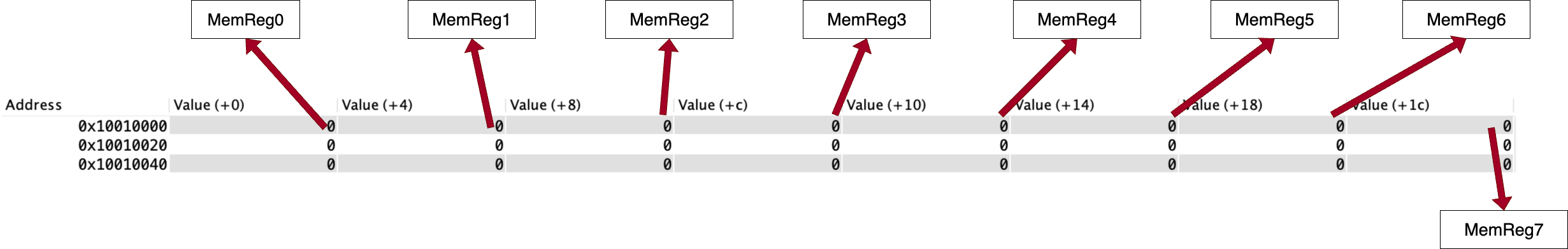
MemReg0 has the address 0x10010000,
corresponding to
RegisterTable[0]
More info about the memory mapped registers can be found in the
RegisterTable description in
the
Data Structures and Global Variables
section. To visualize the state of the registers, the
PrintRegisterTable helper function is provided (see the
Helper Functions section for more
info).
Branch Prediction
Branch prediction is a technique used to improve the performance of a CPU by predicting the outcome of a branch instruction before it is executed. This allows the pipeline to continue executing instructions without waiting for the branch instruction to be resolved. There are two main types of branch prediction:
- Static branch prediction: The outcome of the branch instruction is predicted based on the instruction itself without considering the history of previous branch instructions.
- Dynamic branch prediction: The outcome of the branch instruction is predicted based on the history of previous branch instructions. The CPU can adapt to the program's behavior and improve the accuracy of the predictions.
This lab implements a static branch predictor that always predicts that the branch is NOT taken.
More details about the branch predictor are in the Branch Prediction section.
Memory Delays
Memory delays occur when the CPU accesses memory. These delays have many causes, including cache misses, bus contention, and memory limitations, and many more. This lab simulates memory delays by introducing a delay in the pipeline for some memory accesses to show how memory delays affect the performance of the pipeline and how they can be mitigated.
This lab will only represent the memory delays caused by load and store instructions (delays caused by data cache misses). Delays caused by instruction cache misses will not be simulated in this lab.
Stalls
Stalls are delays that occur in the pipeline when an instruction cannot proceed to the next stage. This can happen for a variety of reasons, such as data hazards, control hazards, and memory delays.
In this lab, stalls are implemented by introducing cycle delays. This can either be due to load-use hazards or memory delays in the event of a cache miss. Cache miss delays are described in the Cache Simulator section, and load-use hazard delays are described in the Forwarding and Data Hazards section.
The Simulator
The simulator is a RISC-V assembly program that models the operation of a pipelined CPU. It is organized into several components, each responsible for a specific stage or operation in the instruction flow.
- Cycle-by-cycle simulation: Each cycle represents the advancement of instructions through the pipeline stages (IF, ID, EX, MEM, WB).
- Parallel execution: Multiple instructions can be in different pipeline stages simultaneously, reflecting real CPU pipelining.
- Test cases: The simulator is tested using self-contained RISC-V assembly programs whose only input is a pointer to the SimulatedMemory region. See the Test Cases section for details.
- Performance metrics: The simulator collects and displays key statistics to help analyze pipeline efficiency and behavior. This is mentioned in the Output section.
These metrics enable detailed analysis of how hazards, stalls, and cache behavior impact CPU performance.
The simulator allows the user to step through the execution of a program instruction by instruction, visualizing how each instruction moves through the pipeline stages: Instruction Fetch (IF), Instruction Decode/Register Fetch (ID), Execute/Address Calculation (EX), Memory Access (MEM), and Write Back (WB). The user can observe how instructions overlap in the pipeline, and how the pipeline handles different types of hazards, such as data hazards (when an instruction depends on the result of a previous instruction), control hazards (caused by branches), and structural hazards (when hardware resources are insufficient). The simulator models cache behavior. When a memory instruction (load or store) is executed, the simulator checks for cache hits and misses, and introduces memory delays (stalls) when a miss occurs. This limited simulation of a memory hierarchy models memory-access delays propagating through the pipeline and affecting the execution of instructions.
The simulator operates on a cycle-by-cycle basis, with the 5 stages of the pipeline implemented as separate functions. These functions are called in reverse order during each cycle, i.e the WriteBackStage is called before the MemoryStage, the MemoryStage is called before the ExecutionStage, and so on. The simulator calls the functions in this order:
  WriteBackStage();
  MemoryStage();
  ExecutionStage();
  DecodeStage();
  InstructionFetchStage();
This approach ensures that the pipeline stages are processed correctly, as later stages depend on the results of earlier ones.
Pipeline Stages
The pipeline is divided into five distinct stages, each of which performs a specific operation on the instruction in that stage. The output of one stage becomes the input of the next stage. The pipeline is designed to allow multiple instructions to be in different stages of execution at the same time. These stages are executed in parallel for different instructions to increase throughput. In the simulator, each of these stages is implemented as a separate subroutine. Each stage is described below.
1. Instruction Fetch (IF) Stage
What it does:
-
Fetch Instruction from Memory:
Uses the current
PCto read the 32-bit instruction from instruction memory. This is a raw retrieval of bits, without interpretation. -
Compute Next
PCTypically adds 4 to the
PC(for sequential flow) to point to the next instruction. Taken branches will override thePCin the Execute stage. -
Write to IF/ID Latch:
Stores the fetched instruction and the current PC into the IF/ID latch, and sets the valid bit to indicate that a real instruction is present.
-
Maintain Steady Flow:
Under normal operation, supplies a new instruction to the decode stage each cycle.
2. Instruction Decode (ID) Stage
What it does:
-
Instruction Type Identification:
Examines opcode and function fields to classify instruction format (R, I, S, SB, etc.). This classification determines how to interpret the other bits and which control signals will be needed.
-
Set Control Signals:
Based on the decoded instruction type, the stage sets the appropriate control signals (such as
RegWrite,MemRead,MemWrite,ALUSrc, etc.) for each instruction type. These signals are packed into a bitfield and passed to later pipeline stages to control their behavior. -
Field Extraction:
Extracts source and destination register indices (
rs1,rs2,rd), immediate values (with proper sign extension), and funct3 fields. The positions of these fields vary by instruction format.This stage does not extract the values that the register holds since data might need to be forwarded. Data gets forwarded to the Execute stage, and the logic for forwarding and load-use hazard detection is in the Execute stage (not in the Decode stage).
-
Write to ID/EX Latch:
Packages all decoded information — register indices, operand values, immediate, instruction type, funct3, control signals — into the ID/EX latch and sets its valid bit. This prepares the Execute stage with everything needed.
Refer to the Control Signals section for more information on the Control Signals mentioned above
3. Execute (EX) Stage
What it does:
-
ALU Operations:
Performs arithmetic and logical operations (e.g., add, sub) on input operands that were fetched in the Decode stage.
-
Effective Address Calculation:
Computes memory addresses for load/store instructions by adding the base register to the offset. The computed memory address is used in the Memory Access stage.
-
Branch Evaluation:
Compares register values for conditional branches (e.g.,
beq,bne) to determine if the branch is taken. If the branch is taken, the target address is computed and written to the program counter. -
Hazard Detection:
Detects data hazards (e.g., when a source register is awaiting update by an earlier instruction in the pipeline). If a hazard is detected, the stage triggers a stall by introducing a bubble (NO-OP), ensuring the pipeline avoids using stale data. The NO-OP represents a no-operation that occurs in the pipeline during a stall, allowing the pipeline to proceed without altering the state.
The NO-OP instruction is NOT inserted in the pipeline but a squashed instruction is converted into a NO-OP in the event of a branch misprediction. More details on this can be found in the Branch Prediction section.
-
Flag Setting and Forwarding:
Sets comparison flags for branches. In hardware, results may be forwarded to dependent instructions to reduce hazards. More information on branch prediction and forwarding can be found in the Branch Prediction section. There are flags that can be used to resolve load-use hazards. More information on flags and global variables can be found in the Global Variables section.
4. Memory Access (MEM) Stage
What it does:
-
Effective Address Usage:
The address for a load or store is used to access memory. The address was previously computed in the Execute stage.
-
Load Operations:
For load instructions (e.g.
lw), the hardware issues a read at the computed address. The data path may wait for cache or memory response; on a hit, data returns quickly, while a miss may cause multi-cycle delays and pipeline stalls. In this lab, loads and stores can result in delays because of data cache misses. Not all memory accesses result in a delay; the percentage of memory accesses that cause a delay is determined by the cache miss rate. In this lab, the occurrence of cache misses are simulated with pseudo-random number generator (see the Cache Simulator section for more info). -
Store Operations:
For store instructions (e.g.
sw), hardware places the data and address on the memory interface. Often, stores can be buffered, allowing the pipeline to continue while the write completes in the background. Correct ordering ensures that subsequent loads see the updated data. -
Interaction with Memory Hierarchy:
The MEM stage interacts with caches or main memory, handling hits and misses. In the case of a cache miss in this lab, the MEM stage stalls the pipeline for 3 cycles to indicate a delay caused by the cache miss.
-
Forwarding Considerations:
For load-use hazards, data becomes available only after this stage; hardware may forward the loaded value directly to dependent instructions to reduce stalls. The MEM stage must place the data on forwarding paths at the correct time.
5. Write Back (WB) Stage
What it does:
-
Check if Write is Needed:
Not every instruction writes to a register. For example, a store instruction or a branch instruction do not write to a register. The
RegWritecontrol signal determines whether this instruction should write back to the register file. -
Choose the Correct Value:
Results can come from different sources:
-
ALU result (e.g., for arithmetic instructions like
add,addi). -
Memory output (e.g., for load instructions like
lw).
The
MemToRegcontrol signal selects between the two options above: ifMemToRegis set to 1, the value from memory is used; otherwise, the ALU result is used. -
ALU result (e.g., for arithmetic instructions like
-
Select the Destination Register:
The destination register index (rd) is propagated through the pipeline to the MEM/WB latch. If
rdisx0(registerzero), the write is not performed because thezeroregister is hard-wired to zero and cannot be modified. -
Write the Value:
Write into the register file at the index specified by
rd.
Summary table of the pipeline stages
| Stage | Full Name | Purpose | Simulator Function |
|---|---|---|---|
| IF | Instruction Fetch | Loads instruction from memory using PC, stores it in IF/ID latch | InstructionFetchStage |
| ID | Instruction Decode | Decodes instruction fields, reads registers, generates control signals | DecodeStage |
| EX | Execute | Performs ALU operation or branch decision | ExecutionStage |
| MEM | Memory Access | Reads/writes memory or updates PC for branches | MemoryStage |
| WB | Write Back | Writes results to the register file | WriteBackStage |
Pipeline Latches
In a real pipelined processor, each stage passes values to the next using pipeline registers. These are small fast registers that "latch" or hold the outputs of one stage so they can be used as inputs to the next stage in the next cycle. In the simulator, each latch is represented as a reserved block of memory that stores instruction data, computed values, and control signals.
Do not clear the latches at the end of each stage. The values in the latches should be preserved across cycles to allow the pipeline to function correctly.
The simulated pipeline in this lab uses four latches:
- IF_ID_LATCH: connects the InstructionFetchStage and DecodeStage
- ID_EX_LATCH: connects the DecodeStage and ExecutionStage
- EX_MEM_LATCH: connects the ExecutionStage and MemoryStage
- MEM_WB_LATCH: connects the MemoryStage and WriteBackStage
Each latch is structured like a C-style struct. Below is a breakdown of each latch, their usage, and the fields they contain.
struct IF_ID_LATCH {
  unsigned instn;   // 32-bit instruction word
  int      pc;      // Program counter at fetch
  byte     valid;   // Valid bit (1 = valid, 0 = invalid/bubble)
};| Field name | Offset (bytes) |
Field size (bytes) |
|---|---|---|
| IF_ID_LATCH.instn | 0 | 4 |
| IF_ID_LATCH.pc | 4 | 4 |
| IF_ID_LATCH.valid | 8 | 1 |
Used for: Passing the instruction and its PC from the Instruction Fetch (IF) stage to the Instruction Decode (ID) stage.
When filled: During IF stage, after fetching an instruction from memory.
When read: In the ID stage. If
valid is 0, the decode stage treats it as a NOP
(bubble).
struct ID_EX_LATCH {
  unsigned   instn;           // 32-bit instruction word
  int        instn_type;      // Instruction type code (0 = R, 1 = I, 2 = S, 3 = SB)
  int        pc;              // Program counter
  int        rd;              // Destination register index
  int        rs1;             // Source register 1 index
  int        rs2;             // Source register 2 index
  int        imm;             // Immediate value
  int        funct3;          // funct3 field
  int        funct7;          // funct7 field (for R-type instructions)
  byte       valid;           // Valid bit (1 = valid, 0 = bubble)
  byte       control_signals; // Packed control signals
};| Field name | Offset (bytes) |
Field size (bytes) |
|---|---|---|
| ID_EX_LATCH.instn | 0 | 4 |
| ID_EX_LATCH.instn_type | 4 | 4 |
| ID_EX_LATCH.pc | 8 | 4 |
| ID_EX_LATCH.rd | 12 | 4 |
| ID_EX_LATCH.rs1 | 16 | 4 |
| ID_EX_LATCH.rs2 | 20 | 4 |
| ID_EX_LATCH.imm | 24 | 4 |
| ID_EX_LATCH.funct3 | 28 | 4 |
| ID_EX_LATCH.funct7 | 32 | 4 |
| ID_EX_LATCH.valid | 36 | 1 |
| ID_EX_LATCH.control_signals | 37 | 1 |
Used for: Passing all decoded information and control signals from the Decode (ID) stage to the Execute (EX) stage.
When filled: In the ID stage after decoding fields and reading register values.
When read: In the EX stage. Used to decide ALU inputs, branch logic, etc.
All operands and control bits are computed here to simplify the EX stage.
struct EX_MEM_LATCH {
  unsigned  instn;           // 32-bit instruction word
  int       instn_type;      // Instruction type code (0 = R, 1 = I, 2 = S, 3 = SB)
  int       rd;              // Destination register index
  int       rs2;             // Source register 2 index
  int       alu_result;      // Result of the ALU operation
  byte      valid;           // Valid bit (1 = valid, 0 = bubble)
  byte      control_signals; // Packed control signals
};| Field name | Offset (bytes) |
Field size (bytes) |
|---|---|---|
| EX_MEM_LATCH.instn | 0 | 4 |
| EX_MEM_LATCH.instn_type | 4 | 4 |
| EX_MEM_LATCH.rd | 8 | 4 |
| EX_MEM_LATCH.rs2 | 12 | 4 |
| EX_MEM_LATCH.alu_result | 16 | 4 |
| EX_MEM_LATCH.valid | 20 | 1 |
| EX_MEM_LATCH.control_signals | 21 | 1 |
Used for: Passing the result of EX stage to the Memory (MEM) stage.
When filled: In the EX stage, after ALU operations and branch target calculations.
When read: In the MEM stage. Used to perform load/store operations
The rs2 field is included in the
EX_MEM_LATCH because sw instructions
read from the rs2
register.
struct MEM_WB_LATCH {
  unsigned  instn;           // 32-bit instruction word
  int       instn_type;      // Instruction type code (0 = R, 1 = I, 2 = S, 3 = SB)
  int       rd;              // Destination register index
  int       alu_out;         // Result of the ALU operation
  int       mem_out;         // Data read from memory (junk if instn is not a load)
  byte      valid;           // Valid bit (1 = valid, 0 = bubble)
  byte      control_signals; // Packed control signals
};| Field name | Offset (bytes) |
Field size (bytes) |
|---|---|---|
| MEM_WB_LATCH.instn | 0 | 4 |
| MEM_WB_LATCH.instn_type | 4 | 4 |
| MEM_WB_LATCH.rd | 8 | 4 |
| MEM_WB_LATCH.alu_out | 12 | 4 |
| MEM_WB_LATCH.mem_out | 16 | 4 |
| MEM_WB_LATCH.valid | 20 | 1 |
| MEM_WB_LATCH.control_signals | 21 | 1 |
Used for: Carrying the final result to be written back to the register file.
When filled: In the MEM stage, after reading or writing to memory.
When read: In the WB stage. Used to select between ALU result and memory load value.
The MemToReg control signal selects whether to use
mem_out or alu_out as the final result.
Only set mem_out if the instruction is a load, ie.
the MemRead control signal is enabled. This means
that mem_out is junk for all other instructions,
which is OK because the WriteBack stage only uses the
mem_out value if the MemRead control
signal is enabled.
Storing the Program Counter in the latches
The PC field in the IF_ID_LATCH is passed from the IF stage to the ID stage. In the Decode stage, the PC field in the IF_ID_LATCH is moved to the ID_EX_LATCH.
The reason for propagating the PC value through the IF_ID_LATCH and ID_EX_LATCH is to correctly compute branch targets in the Execute stage. In the Execute stage, the branch offset is added to the value of the PC field in the ID_EX_LATCH to compute the target address for the branch.
The PC field in the IF_ID_LATCH contains the value of the PC at the time the instruction in the Fetch stage was fetched (ie. the value of the PC before incrementing).
Similarly, the PC field in the ID_EX_LATCH contains the value of the PC at the time that the instruction in the Decode stage was fetched.
What the Valid Bit Does
All four latches contain a valid flag. This flag is
critical in simulating the presence or absence of an instruction in a
pipeline stage.
-
valid= 1: The latch contains a real instruction that must be processed. -
valid= 0: The latch is empty or contains a bubble (NOP). The stage should do nothing except for propagating values (instruction, valid bit, etc.) to the next latch.
When flushing, the simulator explicitly sets the
valid bit to 0 to insert a bubble.
Control Signals
The control_signals field is a byte where each of the 8
control signals is represented by a bit. The 8 control signals are as
follows:
| Bit 7 | Bit 6 | Bit 5 | Bit 4 | Bit 3 | Bit 2 | Bit 1 | Bit 0 |
|---|---|---|---|---|---|---|---|
| ALUSrc | MemToReg | RegWrite | MemRead | MemWrite | Branch | ALUOp1 | ALUOp0 |
-
Bit 7:
ALUSrc-
1 if second ALU input is immediate; 0 if it's from register
rs2
-
1 if second ALU input is immediate; 0 if it's from register
-
Bit 6:
MemToReg-
1 if value to be written to
rdcomes from memory; 0 if from ALU
-
1 if value to be written to
-
Bit 5:
RegWrite-
1 if destination register
rdshould be updated
-
1 if destination register
-
Bit 4:
MemRead- 1 for load instructions
-
Bit 3:
MemWrite- 1 for store instructions
-
Bit 2:
Branch-
1 for conditional branch instructions (like
beq)
-
1 for conditional branch instructions (like
-
Bit 1:
ALUOp1- Bit 1 of 2-bit selector for ALU operation logic. 0 if the instruction is not an R type instruction, 1 if the instruction is an R type instruction.
-
Bit 0:
ALUOp0- Bit 0 of 2-bit selector for ALU operation logic. 0 if the instruction is not a branch instruction, 1 if the instruction is a branch instruction.
Each instruction type activates a specific set of control signals,
which are stored compactly together in the
control_signals byte. The control signal encodings for
each instruction type are shown in the table below.
| Instruction Type | ALUSrc | MemToReg | RegWrite | MemRead | MemWrite | Branch | ALUOp1 | ALUOp0 | Binary | Hex Value |
|---|---|---|---|---|---|---|---|---|---|---|
| R-type | 0 | 0 | 1 | 0 | 0 | 0 | 1 | 0 | 00100010 | 0x22 |
I-type (lw) |
1 | 1 | 1 | 1 | 0 | 0 | 0 | 0 | 11110000 | 0xF0 |
I-type (addi) |
1 | 0 | 1 | 0 | 0 | 0 | 0 | 0 | 10100000 | 0xA0 |
| S-type | 1 | 0 | 0 | 0 | 1 | 0 | 0 | 0 | 10010000 | 0x88 |
| SB-type | 0 | 0 | 0 | 0 | 0 | 1 | 0 | 1 | 00000101 | 0x05 |
Control signals are set in the DecodeStage and stored in the ID_EX_LATCH. The control signals are carried through to the EX_MEM_LATCH and MEM_WB_LATCH in the simulator to control each later stage. Below is a breakdown of which control signals are used in each stage:
-
EX Stage:
ALUSrc,ALUOp1,ALUOp0 -
MEM Stage:
MemRead,MemWrite,Branch -
WB Stage:
RegWrite,MemToReg
This is different from how a real pipelined CPU works, where control signals are generated by a control unit and not passed through latches. However, in this lab, the simulator sets the control bits in the Decode stage based on the instruction type and passes them through the subsequent latches to simulate how a real CPU would handle control signals.
The lab solution must correctly set the
control_signals field in the latches for all supported
instructions.
To simplify the Execution stage logic, read the
instn_type field from the
ID_EX_LATCH to determine the
type of the instruction.
It is possible to use bitmasks to determine the type of instruction
based on the control signals, but using the instn_type
field is easier.
Simulating Cache Hits and Misses
Linear Congruential Generator (LCG)
Cache is small, fast memory that stores frequently accessed data to speed up access times. In this lab, the simulation of cache hits and misses is required in the pipeline simulator. Hits and misses are simulated using the Linear Congruential Generator (LCG) pseudo-random number generating algorithm.
Below is the formula for the LCG, which must be implemented in
PipeliningSimulator.s.
The seed is the initial value of \( X_n \) which is set by
Common.s. The constants \( a \), \( c \), and \( m \) are
predefined in Common.s —
DO NOT CHANGE THEM. The task is to implement
SimulateHitOrMiss, which
computes \( X_{n+1} \) using the formula above and updates \( X_n \)
with this new value each time the LCG is called.
The LCG is used to generate a pseudo-random number. During a memory
access, the simulator will generate a random number using the LCG, and
then compare it to the global variable
CacheMissRate (defined in
Common.s).
- If the random number generated by the LCG is less than CacheMissRate, then it is a cache miss.
- If the random number is greater than or equal to CacheMissRate, then it is a cache hit.
Delays due to Cache Hits and Misses
The simulator must simulate the delays caused by cache hits and misses. In this lab, there is no penalty for a cache hit: in the event of a cache hit, the cycle count is incremented by 1 as usual. Cache miss delays are simulated by stalling the pipeline for CacheMissDelay cycles in the event of a cache miss.
In the event of a cache hit, increment NumCacheHits by 1.
In the event of a cache miss:
- Increment NumCacheMisses by 1
- Set CacheMissDelayStatus to the value of the CacheMissDelay constant. The CacheMissDelayStatus is used by PipeliningSimulator to simulate stall behaviour, as explained in the PipeliningSimulator description.
- Perform the memory access.
For more implementation info, see the PipeliningSimulator, MemoryStage, and SimulateHitOrMiss descriptions.
Forwarding and Data Hazards
Data hazards occur when an instruction depends on the result of a previous instruction that has not yet completed. Forwarding is a technique used in pipelined CPUs to resolve data hazards by allowing the output of one stage to be used as input to another stage before it is written back to the register file. In this lab, forwarding is handled in the ExecutionStage.
In the ExecutionStage, the
simulator checks if the rs1 register index and/or
rs2 register index of the instruction in the Execute
stage matches the rd register index of the instruction in
the Memory stage, the rd register of the instruction in
the Memory stage is not the zero register, and the
instruction in the Memory stage is not a
lw. If so, the instruction in the Execute stage must read
the updated value of the rd register from the
alu_out field of the
MEM_WB_LATCH instead of
accessing the RegisterTable,
allowing the pipeline to proceed without stalling.
A load-use hazard is a type of data hazard. A
load-use hazard occurs if a load instruction is immediately followed
by an instruction that reads from the rd register of the
load instruction.
To detect a load-use hazard, the
ExecutionStage checks if
the rs1 register index and/or rs2 register
index of the instruction in the Execute stage matches the
rd register index of the instruction in the Memory stage,
the rd register of the instruction in the Memory stage is
not the zero register, and the instruction in the Memory
stage is a lw.
In the case of a load-use hazard, the instruction in the Execute stage
must read the updated value of the
rd register from the mem_out field of the
MEM_WB_LATCH instead of
accessing the RegisterTable
(see note below for why this wouldn't work in an actual
pipeline).
For example, if the instruction
lw t0, 0(s0) is in the Memory stage and the instruction
addi t1, t0, 1 is in the Execute stage, this is a
load-use hazard. To deal with the hazard, the
ExecutionStage function should get the value of
t0 from the rd field of the
MEM_WB_LATCH, instead of
reading the old value of t0 from
RegisterTable[5].
Below is the pseudocode logic for determining when to forward in this lab:
if (EX/MEM.RegWrite && EX/MEM.RegisterRd != zero) {
  if (EX/MEM.RegisterRd == ID/EX.RegisterRs1) {
    forward rs1;
  }

  if (EX/MEM.RegisterRd == ID/EX.RegisterRs2) {
    forward rs2;
  }
}
This is not how load-use hazards are resolved in a real pipeline
because, in reality, each stage is executed simultaneously. However,
load-use hazards can be resolved using forwarding in the simulator
because the functions for the stages are called in reverse order: the
MemoryStage function is called
before the
ExecutionStage function, so
the updated rd value is available in the
mem_out field of the
MEM_WB_LATCH by the time the
instruction in the Execute stage needs to access it.
In a real pipeline, load-use hazards cannot be resolved by
forwarding alone.
NO-OPs
This lab also introduces the concept of pipeline NO-OPs. In this lab, NO-OPs are inserted into the pipeline only in response to branch mispredictions, as described below in the Branch Prediction section.
Representing NO-OPs in the Simulator
To change an instruction to a NO-OP, set the valid bit of
the latch that precedes the squashed stage to 0 and set
the element in
CurrentPipeline that
precedes the squashed stage to -2.
For example, to represent a NO-OP in the Decode stage, the
valid bit of the
ID_EX_LATCH is set to
0 and CurrentPipeline[0] is set to
-2. When the
DecodeStage function is
called, it will do nothing because the valid bit of the
ID_EX_LATCH is 0.
When the
InstructionFetchStage
function is called, the -2 will be moved to
CurrentPipeline[1] by InsertIntoPipeline, so
that when PrintPipeline is
called the bubble will correctly be printed in the Decode stage.
Branch Prediction
The simulator uses a simple static prediction strategy: it predicts that all branches are not taken. In this lab, branch mispredictions are handled by the Execute stage of the pipeline. When a branch misprediction occurs, the simulator must perform no operation in the Decode stage and fetch the branch target instruction in the Fetch stage. This ensures that no incorrectly fetched instructions are executed.
In this lab, when a branch instruction is encountered in the ExecutionStage function, NumBranches is incremented by 1 to count the number of executed branch instructions.
If the ExecutionStage function determines that the branch is predicted correctly (i.e. it is not taken), CorrectBranchPredictions is incremented by 1 to count the number of correct branch predictions.
Otherwise, if the ExecutionStage function determines that the branch is not predicted correctly (i.e. it is taken), the following occurs:
- BranchMispredictions is incremented by 1 to count the number of branch mispredictions
- Clock is incremented by 1 to represent the branch misprediction penalty
-
The
validbit of the IF_ID_LATCH is set to 0 to indicate a bubble in the Decode stage - The PC is set to the computed branch target address
-
CurrentPipeline[0] is set to
-2to visualize the bubble in the Decode stageWhen the InstructionFetchStage function is called and the branch target instruction is fetched, the
-2will be moved to CurrentPipeline[1] by InsertIntoPipeline, so that when PrintPipeline is called the bubble will correctly be printed in the Decode stage.
The simulator must keep track of the number of correct and incorrect predictions, as described in the ExecutionStage function description. These statistics can be used to evaluate the effectiveness of the branch prediction mechanism.
For more implementation details, see the ExecutionStage function description.
Functions to be Implemented
The following 8 functions must be implemented as part of the pipelining simulator. The information provided above as well as the details provided in the descriptions for each function are useful for implementing these functions.
Starting with any function is possible, but implementing the functions in the following order is recommended:
- WriteBackStage
- SimulateHitOrMiss
- MemoryStage
- ExecutionStage
- PreDecode
- DecodeStage
- InstructionFetchStage
- PipeliningSimulator
#----------------------------------------------------------------------------
# Simulates the execution of a RISC-V instruction stream through a
# 5-stage pipeline.
#
# Arguments:
# 	a0: address of IF/ID latch
# 	a1: address of ID/EX latch
# 	a2: address of EX/MEM latch
# 	a3: address of MEM/WB latch
#
# Returns:
# 	None
#----------------------------------------------------------------------------
Purpose: Orchestrates the entire pipelined CPU simulation, calling each stage in order, managing pipeline state, and producing output and statistics.
-
Increment the Clock
The simulator must increment Clock by 1 in each iteration of the
PipeliningSimulatorsimulation loop. -
Call Each Stage in Reverse Order (unless there is an ongoing cache miss delay)
If CacheMissDelayStatus is -1 (meaning that there is no ongoing cache miss delay), the simulator must call each stage in reverse order: WriteBackStage, MemoryStage, ExecutionStage, DecodeStage, and finally InstructionFetchStage. Each stage will read from its respective latch and perform its operations.
If the CacheMissDelayStatus is greater than -1 (meaning that there is an ongoing cache miss delay),
PipeliningSimulatorshould not call any of the five stage functions. -
Print the Pipeline
After calling InstructionFetchStage or skipping all of the stages due to a cache miss delay, call the PrintPipeline helper function to print the current state of the pipeline.
-
Decrement CacheMissDelayStatus by 1 if there is an ongoing cache miss delay
If CacheMissDelayStatus is greater than -1 (indicating that there is an ongoing cache miss delay), decrement CacheMissDelayStatus by 1 after calling PrintPipeline.
-
Detect End of Simulation and Print Register Table and End Statistics
Call the CheckEmpty helper at the end of each simulation loop to determine if the pipeline is empty. If the pipeline is empty, the simulation should end.
At the end of the simulation, the simulator must print the register table and a summary of the statistics for the execution of the program, including the number of cycles, number of instructions executed, and any other relevant statistics. This is done by calling the PrintRegisterTable and PrintEndStats helper functions (in that order).
#----------------------------------------------------------------------------
# WriteBackStage
# Writes result to register file if RegWrite is set and valid.
# Selects value from memory or ALU based on MemToReg
#
# Arguments:
# 	a0: address of MEM/WB latch
#
# Returns:
# 	None (updates the register file as needed)
#----------------------------------------------------------------------------
Purpose: Implements the write-back logic for the
pipeline simulator. This stage checks if the
MEM_WB_LATCH contains a
valid instruction and, if so, determines whether a register write
is required based on the RegWrite control signal.
-
Check Valid Bit
Check the valid bit in the MEM_WB_LATCH. If the valid bit is 0 (indicating a NO-OP in the WriteBack stage), the WriteBack stage should exit without performing any further action.
-
Inspect Control Signals
If the valid bit in the MEM_WB_LATCH is one, read the
RegWritecontrol signal to determine if a register update is required. IfRegWriteis set andrdis notx0, useMemToRegto select either the memory-loaded data or the ALU result for writing. IfMemToRegis set, write the value frommem_out(the loaded data) to the register file at indexrd. Otherwise, write the value fromalu_out(the ALU result). -
Update Register File
Write the selected value into the register file at the index specified by
rd, unlessrdisx0(the zero register).
#----------------------------------------------------------------------------
# MemoryStage
# Handles all memory access operations as determined by the control signals.
# This stage is responsible for performing memory reads or writes using the
# address computed in the EX stage, updating memory access statistics and
# calling SimulateHitOrMiss as needed, and updating the MEM/WB latch.
#
# Arguments:
# a0: address of EX/MEM latch
# a1: address of MEM/WB latch
#
# Returns:
# None (updates MEM/WB latch, updates memory for stores)
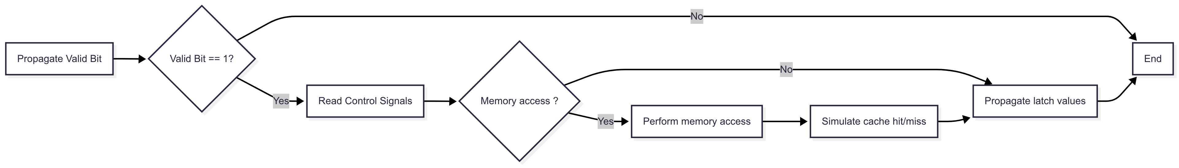
#----------------------------------------------------------------------------Purpose: Implements the memory access logic for load and store instructions, and prepares data for the Write Back stage.
-
Check and Propagate Valid Bit
Check the valid bit in the EX_MEM_LATCH and propagate it to the MEM_WB_LATCH. If the valid bit is 0 (indicating a NO-OP in the Memory stage), the Memory stage should exit without performing any further action.
-
Read Control Signal and Decide Action
Read the control signal from the EX_MEM_LATCH to determine the instruction type (load, store, or other). Only perform memory access if the control signal indicates a memory operation is required.
-
Simulate Memory Access if Instruction is a Load or Store
For load instructions:
- Increment NumMemAccess by 1
- Simulate a cache hit/miss by calling SimulateHitOrMiss
- Increment NumCacheHits or NumCacheMisses by 1 depending on whether the access resulted in a hit or miss
- Set CacheMissDelayStatus to the value of the CacheMissDelay constant in the case of a cache miss
- Read from memory at the computed address
For store instructions:
- Increment NumMemAccess by 1
- Simulate a cache hit/miss by calling SimulateHitOrMiss
- Increment NumCacheHits or NumCacheMisses by 1 depending on whether the access resulted in a hit or miss
- Set CacheMissDelayStatus to the value of the CacheMissDelay constant in the case of a cache miss
- Write the appropriate value to memory at the computed address
For other instructions, no memory access is performed.
-
Write to MEM_WB_LATCH
After handling the instruction, write the relevant data (such as destination register, ALU result, loaded data, and control signals) into the MEM_WB_LATCH, and set the valid bit if this was a real instruction.
The flow chart below is provided to help understand the flow of
the MemoryStage:
#----------------------------------------------------------------------------
# ExecutionStage
# Performs arithmetic, logical, and address calculations based on instruction
# type. This stage is responsible for executing ALU operations for R-type and
# I-type instructions, computing branch conditions, preparing effective
# addresses for S-type instructions, and propagating results and control
# signals to the EX/MEM latch.
#
# Arguments:
# a0: address of ID/EX latch
# a1: address of EX/MEM latch
#
# Returns:
# None (updates EX/MEM latch)
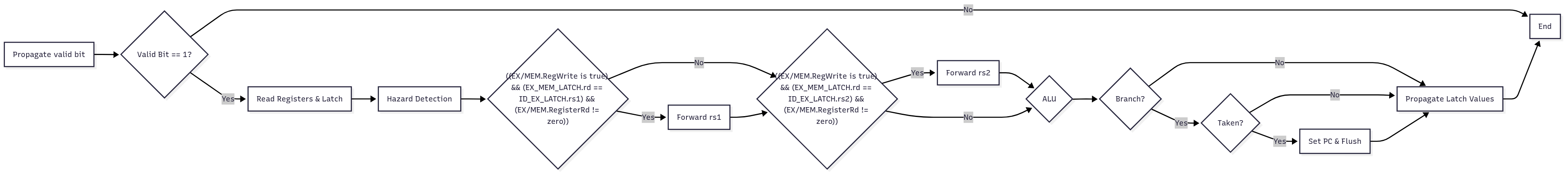
#----------------------------------------------------------------------------Purpose: Executes arithmetic, logic, and branch operations, and prepares results for the Memory stage.
-
Check and Propagate Valid Bit
Check the valid bit in the ID_EX_LATCH and propagate it to the EX_MEM_LATCH. If the valid bit is 0 (indicating a NO-OP in the Execution stage), the Execution stage should exit without performing any further action.
-
Read from ID_EX_LATCH
Read operands, immediate, instruction type, and control signals from the ID_EX_LATCH.
-
Perform Computation
For each instruction type, perform the appropriate computation or operation as required by that instruction. This may include arithmetic or logical operations, address calculations, or comparisons for branches.
For branch instructions, compute the target address and update the program counter (PC) if the branch is taken.
-
Write to EX_MEM_LATCH
After computation, write all required values into the EX/MEM latch to pass necessary data and control information to the next pipeline stage.
-
Update NumInstructions if Instruction is Valid
If the instruction in the Execute stage is valid (its valid bit is 1), increment NumInstructions by 1. This is done to count the number of executed instructions (NO-OPs do not count).
Because NumInstructions counts the number of executed instructions, it makes sense to update it in the Execute stage. However, it is also possible to check the valid bit and update NumInstructions in the Memory stage or the Write Back stage instead.
-
Update NumBranches if Instruction is Branch
If the instruction in the Execute stage is a branch (and is valid), NumBranches should be incremented by 1.
-
Determine Branch Outcome and Handle Branch Mispredictions
In the case of a branch instruction,
ExecutionStagemust determine the branch outcome (ie. whether it is taken or not taken).If the branch is predicted correctly (i.e. it is not taken), CorrectBranchPredictions must be incremented by 1 to count the number of correct branch predictions.
If the branch is mispredicted (ie. it is taken),
ExecutionStagemust:- Increment BranchMispredictions by 1 to count the number of branch mispredictions
- Increment Clock by 1 to represent the branch misprediction penalty
-
Set the
validbit of the IF_ID_LATCH to 0 to indicate a bubble in the Decode stage - Set the PC to the computed branch target address
-
Set CurrentPipeline[0] to
-2to visualize the bubble in the Decode stageAfter the InstructionFetchStage function is called and the branch target instruction is fetched, the
-2will be moved to CurrentPipeline[1] by InsertIntoPipeline, so that when PrintPipeline is called the bubble will correctly be printed in the Decode stage.
-
Perform Forwarding (if necessary)
If the
rs1register index and/orrs2register index of the instruction in the Execute stage matches therdregister index of the instruction in the Memory stage, therdregister of the instruction in the Memory stage is not thezeroregister, and the instruction in the Memory stage is not alw, forward thealu_outvalue from the Memory stage to the Execute stage. -
Detect and Handle Load-Use Hazards
If the
rs1register index and/orrs2register index of the instruction in the Execute stage matches therdregister index of the instruction in the Memory stage, therdregister of the instruction in the Memory stage is not thezeroregister, and the instruction in the Memory stage is alw, there is a load-use hazard.In the case of a load-use hazard, the instruction in the Execute stage must read the updated value of the
rdregister from themem_outfield of the MEM/WB latch instead of accessing the RegisterTable.For example, if the instruction
lw t0, 0(s0)is in the Memory stage and the instructionaddi t1, t0, 1is in the Execute stage, this is a load-use hazard. To deal with the hazard, theExecutionStagefunction should get the value oft0from therdfield of the MEM_WB_LATCH, instead of reading the old value oft0fromRegisterTable[5].This is not how load-use hazards are resolved in a real pipeline because, in reality, each stage is executed simultaneously. However, load-use hazards can be resolved using forwarding in the simulator because the functions for the stages are called in reverse order: the MemoryStage function is called before the
ExecutionStagefunction, so the updatedrdvalue is available in themem_outfield of the MEM_WB_LATCH by the time the instruction in the Execute stage needs to access it. In a real pipeline, load-use hazards cannot be resolved by forwarding alone.
The flow chart below is provided to help understand the flow of
the
ExecutionStage:
#----------------------------------------------------------------------------
# DecodeStage
# Decodes the instruction that was fetched in the preceding stage.
# This stage is responsible for determining the instruction type, extracting
# operand registers, immediates, and funct3 codes, and generating the correct
# control signals for each type of instruction.
#
# Arguments:
# 	a0: address of IF/ID latch
# 	a1: address of ID/EX latch
#
# Returns:
# 	None (updates ID/EX latch)
#----------------------------------------------------------------------------
Purpose: Decodes instructions, extracts operands, and sets up control signals for the Execution stage.
-
Check and Propagate Valid Bit
Check the valid bit in the IF_ID_LATCH and propagate it to the ID_EX_LATCH. If the valid bit is 0 (indicating a NO-OP in the Decode stage), the Decode stage should exit without performing any further action.
-
Classify Instruction Type
Use the GetInstructionType helper function to determine the instruction format (e.g., R-type, I-type, etc.).
-
Extract Fields and Read Operands:
Use the PreDecode function to extract
rs1,rs2(for R, S, and SB-type),rd(for R and I-type), the sign-extended immediate values (for I, S, and SB-type),funct3, andfunct7(for R-type) from the instruction. -
Generate Control Signals
Based on the instruction type and function, generate the correct control signals (indicating memory access, ALU operation, write-back, branch, etc.) and store them together in the ID_EX_LATCH
control_signalsfield. -
Write Decoded Information to ID_EX_LATCH
Write all decoded information (operand values, register indices, immediate, instruction type, control signals, etc) into the ID_EX_LATCH and set its valid bit. This prepares the Execute stage for the next cycle.
#----------------------------------------------------------------------------
# InstructionFetchStage
# Performs the instruction fetch stage by fetching the instruction at the current
# program counter, and performs the operations of the instruction fetch stage
#
# Arguments:
# 	a0: address of IF/ID latch
# 	a1: Program Counter
#
# Returns:
# 	None (updates IF/ID latch and program counter)
#----------------------------------------------------------------------------
Purpose: Fetches the next instruction from memory and updates the program counter (PC).
-
Get Instruction
Load the instruction from the address in memory that is given by the Program Counter stored in
a1. -
Write to IF_ID_LATCH
Store the fetched instruction and the PC into the IF_ID_LATCH. If the fetched instruction is the sentinel value -1, set the valid bit to 0 in the IF_ID_LATCH. Otherwise, set the valid bit to 1 in the IF_ID_LATCH to indicate the presence of a new valid instruction.
In this lab, the fetched instruction having a value of -1 indicates that the end of the program has been reached. The list of instructions ends with five sentinel -1 values, since CheckEmpty only considers the pipeline to be empty when all five instructions in the CurrentPipeline are -1.
-
Insert into CurrentPipeline (for visualization)
Call the InsertIntoPipeline helper to insert the fetched intruction into
CurrentPipeline[0]and shift the other elements of the CurrentPipeline array to the next stage. This ensures that the pipeline visualization reflects the new state of the pipeline. -
Increment PC
Increment the
a1value by 4 and store the incremented value into the PC global variable.
#----------------------------------------------------------------------------
# PreDecode
# Decodes a RISC-V instruction word into its component register indices,
# immediate value, and function codes, depending on the instruction type.
#
# Arguments:
# 	a0: 32-bit hex value of the RISC-V instruction
# 	a1: Integer code indicating the instruction type:
# 		0 - R-type
# 		1 - I-type
# 		2 - S-type
# 		3 - SB-type
#
# Returns:
# 	a0: rs1
# 	a1: rs2 (-1 for I-type)
# 	a2: rd (-1 for S-type and SB-type)
# 	a3: immediate (junk for R-type)
# 	a4: funct3
# 	a5: funct7 (-1 for I-type, S-type, and SB-type)
#----------------------------------------------------------------------------
Purpose: This function decodes a 32-bit RISC-V
instruction into its component fields based on the instruction
type. PreDecode is called in the
DecodeStage to extract
register indices, immediate values, and function codes.
For SB-type instructions, PreDecode should call the
GetBranchImm helper
function to determine the immediate.
#----------------------------------------------------------------------------
# SimulateHitOrMiss
# Simulates a cache hit or miss for a given register using a
# Linear Congruential Generator (LCG). Updates global counters for cache
# hits and misses.
#
# Arguments:
# 	a0: Address of the Memory access
#
# Returns:
# 	a0: 1 if cache hit, 0 if cache miss
#----------------------------------------------------------------------------
Purpose: Models cache behavior for memory accesses, affecting pipeline stalls and statistics. This function is called in the MemoryStage.
Takes in a0, the address of the memory access.
However, this argument is not used within the
function: it is just there to visualize actual cache behavior.
-
Update
X_nCompute the next value of X_n using the LCG formula:
\[ X_{n+1} = (a \cdot X_n + c) \bmod m \]And update the X_n global variable with the new value.
Use the a, c, and m global variables for the constant values in the LCG formula.
-
Determine if Access was Hit or Miss
Compare the updated X_n value to the CacheMissRate constant. If the updated X_n value is less than the CacheMissRate constant, it is a cache miss; otherwise, it is a cache hit.
Return 1 for a hit, or 0 for a miss.
When this function returns 0, the simulator will simulate a delay in the execution of the pipeline; when it returns a 1, the execution proceeds without delays.
Helper Functions
#----------------------------------------------------------------------------
# GetInstructionType (helper)
# Determines the instruction type by examining the instruction's opcode
# to classify the instruction as R, I, S, or SB type.
#
# Input:
# 	a0: 32-bit instruction (hex format)
#
# Output:
# 	a0: Integer code indicating the instruction type:
# 		0 - R-type
# 		1 - I-type
# 		2 - S-type
# 		3 - SB-type
#----------------------------------------------------------------------------
Purpose: Decodes the opcode of a 32-bit RISC-V
instruction to determine its type. It returns an integer that
indicates the instruction format, which is used in the Decode
stage to correctly decode the instruction. This value is passed
through the ID_EX_LATCH,
EX_MEM_LATCH, and
MEM_WB_LATCH in the
instn_type field for the Execution, Memory, and
WriteBack stages to use as needed.
Usage: Called in DecodeStage to classify instructions and set up control signals and field extraction logic.
#----------------------------------------------------------------------------
# GetBranchImm (helper)
# Gets the value of the immediate for a branch instruction
#
# Arguments:
# 	a0: an SB (branch) instruction word
#
# Returns:
# 	a0: a sign extended immediate
#----------------------------------------------------------------------------
Purpose: Extracts and sign-extends the immediate value from a 32-bit SB-type (branch) RISC-V instruction. This function is needed because, in RISC-V, the immediate is encoded in a non-contiguous set of bits and must be assembled and sign-extended for use in branch target calculations.
Usage: Called in PreDecode to determine the immediate for computing the branch target address for branch instructions.
#----------------------------------------------------------------------------
# PrintPipeline (helper)
# Prints the mnemonic of each instruction currently in the pipeline
# by iterating over the CurrentPipeline array.
#
# Arguments:
# 	None
#
# Returns:
# 	None (output is printed to console)
#----------------------------------------------------------------------------
Purpose: Prints the current state of the
pipeline, showing the mnemonics of the instruction in each stage
(eg. addi is a mnemonic).
PrintPipeline iterates through the
CurrentPipeline array
to display the pipeline's status.
Usage: Called at the end of the simulation loop in PipeliningSimulator to print the pipeline state after each cycle.
#----------------------------------------------------------------------------
# CheckEmpty (helper)
# Determines whether the instruction pipeline is empty by checking if
# every element of the CurrentPipeline array is -1.
#
# Arguments:
# 	None
#
# Returns:
# 	a0: 1 if all pipeline places are empty (-1), 0 otherwise
#----------------------------------------------------------------------------
Purpose: Checks if the pipeline is empty by iterating through the CurrentPipeline array and checking if all elements are equal to the sentinel value (-1). Returns 1 if all pipeline slots are empty, and -1 otherwise.
Usage: Called at the end of the simulation loop in PipeliningSimulator after PrintPipeline to check if the simulation should end.
#----------------------------------------------------------------------------
# InsertIntoPipeline (helper)
# Inserts an instruction into the first place of the CurrentPipeline array.
# Shifts all existing instructions to the next place in the CurrentPipeline
# array to make space for the new instruction. The last instruction in the
# CurrentPipeline array is discarded (it is retired).
#
# Arguments:
# 	a0: 32-bit instruction to InsertIntoPipeline into the pipeline
#
# Returns:
# 	None (updates the CurrentPipeline array)
#----------------------------------------------------------------------------
Purpose: This function inserts a new instruction into the CurrentPipeline array at the first stage (IF) and shifts all other instructions to the right.
-
Shift Instructions
Starting from the last stage (WriteBack), shift each instruction in the CurrentPipeline array to the next stage (to the right). This ensures that the pipeline stages are updated correctly. The instruction in the WriteBack stage is retired and all the other instructions are shifted to their subsequent stages. For example, the instruction in the Fetch stage moves to the Decode stage, the instruction in the Decode stage moves to the Execute stage, and so on. This means that the instruction in
CurrentPipeline[0](IF) will be moved toCurrentPipeline[1](ID), and so on. -
Insert New Instruction
Place the new instruction (provided in
a0) into the first stage (IF) of the CurrentPipeline array.
This function is essential for maintaining the state of the CurrentPipeline and ensuring that instructions flow correctly through the stages.
This function is strictly used to update the CurrentPipeline array in order to visualize the current state of the pipeline. It is not used to implement the pipeline stages.
#----------------------------------------------------------------------------
# PrintRegisterTable (helper)
# Prints the values of all 32 registers in a tabular format.
#
# Arguments:
# 	a0: address of register table
#
# Returns:
# 	None
#----------------------------------------------------------------------------
Purpose: Prints out the values of all 32 registers, showing the current state of the register table. Takes in the address of the register table as an argument.
Usage: Used for displaying the register table at the end of the PipeliningSimulator before PrintEndStats is called. Also useful for debugging.
#----------------------------------------------------------------------------
# PrintEndStats (helper)
# Prints out the final statistics of the simulation, including CPI,
# memory access statistics, branch prediction statistics, and cache
# performance statistics.
#
# Arguments:
# 	None
#
# Returns:
# 	None
#----------------------------------------------------------------------------
Purpose: Prints the final statistics of the simulation, including CPI, memory access statistics, branch prediction statistics, and cache performance statistics.
Usage: Used for the displaying the final visual statistics of the simulation at the end of the PipeliningSimulator after PrintRegisterTable is called.
Data Structures and Global Variables
The simulator uses several global variables and data structures to manage the pipeline state, control signals, and instruction flow.
The pipeline latches are explained in detail in the Pipeline Latches section above, so they are not described here.
Additional data structures may be added as needed, but the existing data structures must be used.
This data structure is an array, where each element in the array represents a stage in the pipeline. Each stage (or element in the array) holds the 32-bit binary encoding (shown in hexadecimal format) of the instruction currently being processed in that stage.
Example:
| Stage | IF | ID | EX | MEM | WB |
|---|---|---|---|---|---|
| Instruction (hex) | 0x00140413 | 0x00629e63 | 0x00c2ab03 | 0x008f2023 | 0x00628663 |
Each column shows the instruction (in hexadecimal) currently in that pipeline stage.
For example, 0x00140413, which is the binary
representation of addi s0, s0, 1, is in the
Instruction Fetch Stage. 0x00629e63, which is the
binary representation of beq t0, t1, 28 is in the
Instruction Decode Stage, and so on.
This data structure is only used to visualize the pipeline state in the simulator. It is NOT used for the actual simulation implementation. Do NOT use the instructions in this data structure to implement the pipeline stages.
Clock counts the number of clock cycles from the
beginning of the simulation.
Clock is incremented every cycle. It is also used for
calculating the CPI.
The Clock is additionally incremented by 1 in the
case of a branch misprediction, as described in the
Branch Prediction
section.
The value of Clock is printed as the "Number of
Cycles" by the
PrintEndStats helper at
the end of the simulation.
NumInstructions counts the total number of
executed valid instructions (not including NO-OPs).
The value of NumInstructions is printed as the
"Number of Instructions Executed" by the
PrintEndStats helper at
the end of the simulation.
NumMemAccess counts the number of memory accesses
that have occurred.
The value of NumMemAccess is printed as the "Number
of Memory Accesses" by the
PrintEndStats helper at
the end of the simulation.
This counts the total number of times that memory was accessed, which includes both loads and stores.
NumBranches counts the total number of branch that
have been executed during the simulation.
The value of NumBranches is printed as the "Number of
Branches Executed" by the
PrintEndStats helper at
the end of the simulation.
CorrectBranchPredictions counts the number of
branches that were predicted correctly by the static branch
predictor.
The value of CorrectBranchPredictions is printed as
the "Number of Correct Branch Predictions" by the
PrintEndStats helper at
the end of the simulation.
BranchMispredictions counts the number of branches
that were mispredicted (predicted incorrectly) by the static
branch predictor.
The value of BranchMispredictions is printed as the
"Number of Branch Mispredictions" by the
PrintEndStats helper at
the end of the simulation.
NumCacheHits counts the number of memory accesses
that resulted in a cache hit.
The value of NumCacheHits is printed as the "Number
of Cache Hits" by the
PrintEndStats helper at
the end of the simulation.
NumCacheMisses counts the number of memory
accesses that resulted in a cache miss.
The value of NumCacheMisses is printed as the "Number
of Cache Misses" by the
PrintEndStats helper at
the end of the simulation.
CacheMissRate is a constant that represents the
threshold for determining whether a memory access results in a
cache hit or miss. Do NOT modify
CacheMissRate.
When the number generated by the Linear Congruential Generator
(LCG), X_n, is greater than or
equal to CacheMissRate, it is a cache hit. Otherwise,
it is a cache miss.
This constant is used in the SimulateHitOrMiss function.
For the purposes of the simulation in this lab, the cache miss rate is a constant. However, in a real pipeline, the cache miss rate is not constant; rather, it is a statistic corresponding to the fraction of memory accesses that result in misses.
CacheMissDelayStatus tracks the status of cache
miss delays.
The CacheMissDelayStatus is initially -1. A
CacheMissDelayStatus of -1 indicates that there is no
ongoing cache miss delay.
When a cache miss is detected in
MemoryStage,
CacheMissDelayStatus is set to the value of the
CacheMissDelay
constant. A CacheMissDelayStatus equal to
CacheMissDelay
indicates that a cache miss occured in the current cycle.
After PrintPipeline is
called in the
PipeliningSimulator
function, CacheMissDelayStatus is decremented by 1 if
CacheMissDelayStatus is greater than -1.
If CacheMissDelayStatus is greater than -1 at the
start of the
PipeliningSimulator
simulation loop (indicating an ongoing cache miss delay),
PipeliningSimulator
must skip calling the stage functions (but
PrintPipeline must still
be called), as explained in the
PipeliningSimulator
description.
CacheMissDelay is a constant that represents the
number of cycles that the pipeline is stalled due to a cache
miss. Do NOT modify CacheMissDelay.
It is used to determine how long the pipeline should be stalled
when a cache miss occurs. This value is set to 3 in
Common.s.
PC (Program Counter) holds the address of the next
instruction to be fetched from memory.
The PC is updated in the
InstructionFetchStage
to point to the next instruction. By default, it increments by 4
(the size, in bytes, of a 32-bit RISC-V instruction) for
sequential execution. However, it may be updated to a branch
target address in the case of a taken branch.
The PC plays a critical role in ensuring correct
program execution.
The RegisterTable represents the state of the
registers in the simulator.
The RegisterTable is used to simulate the CPU's
register file and is essential for executing instructions
correctly. The RegisterTable is represented as an
array that contains the following elements:
| Memory-Mapped Register |
RISC-V Register | ABI Name | Description |
|---|---|---|---|
| RegisterTable[0] | x0 | zero | Hard-wired zero |
| RegisterTable[1] | x1 | ra | Return address |
| RegisterTable[2] | x2 | sp | Stack pointer |
| RegisterTable[3] | x3 | gp | Global pointer |
| RegisterTable[4] | x4 | tp | Thread pointer |
| RegisterTable[5-7] | x5–x7 | t0–t2 | Temporaries |
| RegisterTable[8] | x8 | s0/fp | Saved/frame pointer |
| RegisterTable[9] | x9 | s1 | Saved register |
| RegisterTable[10-11] | x10–x11 | a0–a1 | Args/return values |
| RegisterTable[12-17] | x12–x17 | a2–a7 | Function arguments |
| RegisterTable[18-27] | x18–x27 | s2–s11 | Saved registers |
| RegisterTable[28-31] | x28–x31 | t3–t6 | Temporaries |
Each element of the RegisterTable array is a
memory-mapped register. For example,
RegisterTable[1]
corresponds to the return address (ra) memory-mapped
register.
X_n represents the current value in the Linear
Congruential Generator (LCG).
X_n is updated in
SimulateHitOrMiss
using the formula:
The initial value of X_n is the seed, which is set to
0 in Common.s.
Do NOT change the initial value of X_n
(but the solution requires overwriting X_n in
SimulateHitOrMiss).
a is the multiplier constant in the LCG
formula.
a is used for the LCG formula in
SimulateHitOrMiss.
a determines the rate of change in the sequence of
pseudo-random numbers generated. a is set to 2 in
Common.s.
Do NOT modify a.
c is the increment constant in the LCG
formula.
c is used for the LCG formula in
SimulateHitOrMiss.
c ensures that the sequence of pseudo-random numbers
generated does not repeat prematurely. c is set to 1
Common.s.
Do NOT modify c.
m is the modulus constant in the LCG
formula.
m is used for the LCG formula in
SimulateHitOrMiss.
m defines the range of the pseudo-random numbers
generated. m is set to 101 in Common.s.
Do NOT modify m.
SimulatedMemory is a pointer to a contiguous,
word-aligned area of memory (256 bytes in size) that simulated
programs can store to and load from.
SimulatedMemory is allocated in
Common.s. Common.s sets memory-mapped
register x11 (a0) in the
RegisterTable to the
value of SimulatedMemory (ie. the pointer to the
simulated memory region), so that simulated programs can access
this area. This is necessary because the simulated program does
not have access to the global variables in Common.s,
so test cases cannot access the
SimulatedMemory global variable directly.
In test cases, lw and sw
instructions may only access memory addresses in the
SimulatedMemory region. Accessing memory outside of this region in test cases is
undefined behaviour.
For more details, see the Test Cases section.
Test Cases
Common.s includes some test cases verify the correctness
of your implementation. However,
the provided test cases are NOT extensive. You must
do your own testing to verify the correctness of your implementation.
The test cases and lab solution support a limited set of RISC-V instructions:
-
The following R-type instructions are supported:
add(add)sub(subtract)
-
The following I-type instructions are supported:
lw(load word)addi(add immediate)
-
The following S-type instructions are supported:
sw(store word)
-
The following SB-type instructions are supported:
beq(branch if equal)bne(branch if not equal)
All test cases are RISC-V assembly files with the
.s extension. Assembler directives (.text,
.include, etc.) and global variables are not supported in
test cases.
Each test case is a self-contained assembly program whose only input
is a pointer to the
SimulatedMemory region.
This pointer is passed to the program via the
a0 memory-mapped register in the
RegisterTable.
The Common.s file is responsible for allocating the 256
byte word-aligned
SimulatedMemory region and
setting up the a0 memory-mapped register in the
RegisterTable to point to
the SimulatedMemory.
In test cases, lw and sw
instructions may only access memory addresses in the
SimulatedMemory region. Accessing memory outside of this region in test cases is undefined
behaviour.
Below is an example of a test case that sums the elements of an array:
The test cases are not exclusively array operations. The goal of the test cases is to verify that your pipelining simulator can handle a variety of instructions and programs. Another example of a test case is given below:
Testing Your Lab
For this lab, there is only one program argument required: the binary
file of the input function (e.g., demo.bin). You must
provide the full path of this file in the program arguments section in
the Execute tab on RARS. Ensure that the path adheres to the following
criteria:
- No quotation marks around the path.
- No spaces in the path or file names.
For example, consider the path
Users/JohnDoe/CMPUT-229/Lab6/Code/Tests/calculatesum.bin
A space in the file path (eg. Lab 6) can cause issues
when trying to locate the file. It is recommended to rename
directories and filenames to a name without spaces (eg.
Lab6 instead of Lab 6) to avoid any issues.
The Common.s file contains some unit tests to help test
the solution. This testing works on a predefined input function and
checks whether the output from functions in
PipeliningSimulator.s matches the expected output. The
tests are hardcoded and do not run on the file specified in the
program arguments. The results of the unit tests can be viewed in the
Run I/O panel of RARS.
Creating Test Cases
To create a test case, first write a RISC-V test function in an assembly file. Use the command:
rars a dump .text Binary input_function.bin input_function.s
The binary file generated by this command can serve as a program
argument in RARS for PipeliningSimulator.s. Use the full
file path, ensuring to specify the binary (.bin) file for
input, not the assembly (.s) file.
Running from the command line
rars nc PipeliningSimulator.s pa input_function.binOutput
The output of the simulator consists of three parts:
- The state of the pipeline at each cycle in a tabular format, displaying the instructions in each stage (IF, ID, EX, MEM, WB). Each row of this table is printed by PrintPipeline, which is called at the end of each iteration of the PipeliningSimulator simulation loop.
- The final state of the RegisterTable, as displayed by the PrintRegisterTable helper function.
- Final pipeline statistics printed by the PrintEndStats helper function, including CPI, memory access statistics, branch prediction statistics, and cache performance statistics.
Example
An example of the simulator's output for the
calculatesum.bin test case is provided below:
Pipeline Stages
The first component of the simulator is a table of pipeline stages, showing the instructions in each stage at each cycle. The output is printed to the run I/O in a tabular format, with each row representing a cycle and each column representing a pipeline stage (IF, ID, EX, MEM, WB). Each row of this table is printed by PrintPipeline, which is called at the end of each iteration of the PipeliningSimulator simulation loop.
Register Table
At the end of the simulation, the final state of the RegisterTable is printed. This shows the final values of all 32 registers after executing the program. The register table is printed in a tabular format by the PrintRegisterTable helper function, with each row of the table containing a register and its value.
Pipeline Analysis and Statistics
The final pipeline statistics printed by the PrintEndStats helper function provide insight into the performance of the simulated pipelined CPU. It includes the following statistics:
- Number of Cycles: The total number of clock cycles required to execute the program from start to finish.
- Number of Instructions Executed: The total number of instructions that were executed (does not include NO-OPs).
-
Cycles Per Instruction (CPI): The average number of
cycles per instruction, calculated using the following formula:
CPI = Number of Cycles / Number of Instructions Executed. - Number of Memory Accesses: The number of memory accesses (loads and stores) that occurred during the simulation.
-
Number of Branches Executed: The number of times a branch instruction was executed.
This includes all executed branches (branches that were taken and branches that were not taken).
- Number of Correct Branch Predictions and Branch Mispredictions: The number of times the static branch predictor made a correct or incorrect prediction. This helps evaluate the effectiveness of the branch prediction strategy and its impact on pipeline performance.
- Number of Cache Hits and Misses: The number of memory accesses that resulted in cache hits or misses. This affects overall performance due to cache miss delays.
Assumptions and Notes
- The simulator assumes that all instructions are valid RISC-V instructions and follow the standard encoding.
- The simulator does not handle exceptions or interrupts; it focuses solely on the pipelining behavior.
- The simulator does not implement any form of cache; all memory accesses are direct to the main memory. The simulator simulates whether each memory access results in a cache hit or miss, but the simulator does not actually implement a cache.
-
As mentioned in the
Test Cases section, only a
limited subset of RISC-V instructions are supported by the
simulator:
-
The following R-type instructions are supported:
add,sub -
The following I-type instructions are supported:
addi,lw -
The following S-type instructions are supported:
sw -
The following SB-type instructions are supported:
beq,bne
-
The following R-type instructions are supported:
- The simulator does not support any form of pipelining optimizations such as out-of-order execution, speculative execution, or advanced branch prediction techniques. The branch prediction is static: branches are always predicted to not be taken, as described in the Branch Prediction section.
Tips and Tricks
Here are some tips and tricks for completing this lab:
-
The solution to the lab requires a lot of
lwandswinstructions. To load a word from a global variable, you do not need to load the address of the variable into a register first. Instead, you can directly load the word using the instructionlwwith the address of the variable as an immediate value. For example, to load the value of the variableNumBranches, you can uselw t0, NumBranches.Similarily, to store the value of the register into a global variable, you can use the instruction
swwith the address of the variable as an immediate value. For example, to store the value of the registert0into the variableNumBranches, you can usesw t0, NumBranches, t1, wheret1is a temporary register that will hold the address of the variable. -
To view the values stored in the latches while debugging, you can use the Labels window in the Execute section of RARS. To see the Labels window, enable the
Settings -> Show Labels Window (symbol table)option:
The Labels window will then appear in the Execute section of RARS:
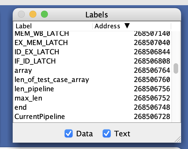
Clicking on a label in the Labels window will take you to the address in memory that the label points to. This is useful for checking the values stored in the latches.
- Use the provided test cases and create your own custom test cases to verify the correctness of your implementation.
- Make sure to read the comments and function headers in the provided code to understand the purpose of each function and variable.
-
A major part of this lab is displaying pipeline statistics. To help verify that your simulator's statistics are correct, you can run a test case assembly file in the RARS simulator and use the Instruction Statistics (in the Tools section of RARS) to view the number of branches, number of memory accesses, and other statistics.
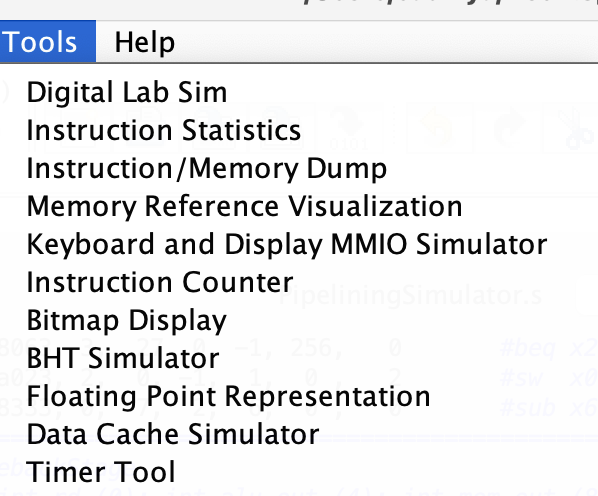
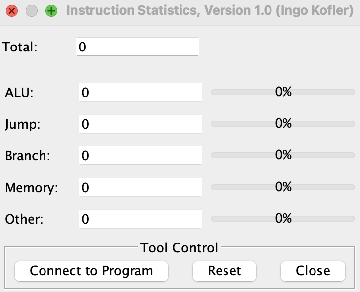
Although the RARS simulator provides the number of cache hits and misses in its Data Cache Simulator, it uses its own cache implementation which is not used in this lab.
-
To verify that the
instnfields of the pipeline latches contain the correct RISC-V instruction, use a RISC-V decoder such as rvcodec.js to convert theinstnbinary representation to a human-readable RISC-V instruction. - Use the RARS simulator's debugging features, such as breakpoints and step-by-step execution, to troubleshoot issues in your code.
- If you encounter any issues or mistakes with the helper functions, refer to the lab documentation or ask the TAs.
Resources
Marking
Assignments too short to be adequately judged for code quality will be given a zero for that portion of the evaluation.
- 38% for the Visual Output
- 20% for the pipelining output
- 13% for the final register table
- 5% for the simulation summary
- 4% for InstructionFetchStage
- 8% for DecodeStage
- 8% for ExecutionStage
- 8% for MemoryStage
- 5% for WriteBackStage
- 2% for SimulateHitOrMiss
- 7% for PreDecode
- 20% for code cleanliness, readability, and comments
Submission
There is a single file to be submitted for this lab
(PipeliningSimulator.s) and it should contain the code
for your solution.
-
Do not add a
mainlabel to this file. - Do not modify the function names.
- Do not remove the CMPUT 229 Student Submission License at the top of the file containing your solution and remember to include your name in the appropriate section of this text.
-
Do not modify the line
.include "Common.s". -
Do not modify the
Common.sfile. - Keep the files in the Code folder of the git repository.
- Push your repository to GitHub before the deadline. Just committing will not upload your code. Check online to ensure your solution is submitted.